 Miroslav Zuzelka
I ordered PCB at ALLPCB.com and they arrived in about 5 days from order. They are, as always, really nice. Just look at them:
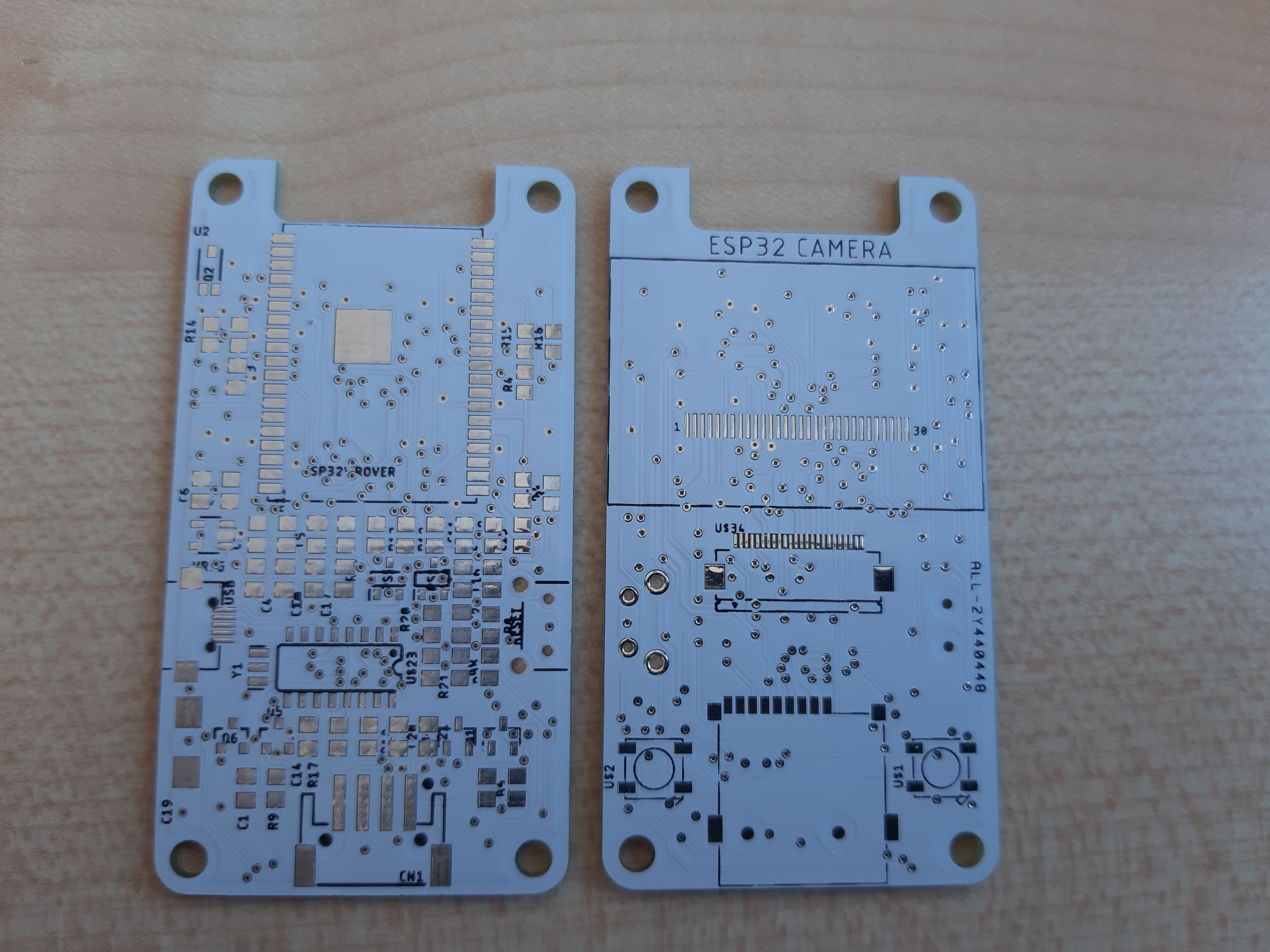
So now, I have to assemble one to find out, if I made some mistake.
I made stencil at my work from Mylar foil and applied solder paste on top side of the board. I placed all parts which I had in that moment (some of them were on order) ,put the board in to my oven and reflowed it. Few caps melted together, but that was not a big deal to repair. I decide to test board before i will go more further.
- USB programming - working
- reset button - working
- light sensor - partly working. Values from reading were in really narrow scope and after some debugging, I changed value of a resistor and it was nicely reading scope from 0 to 4095.
light sensor -> working
OK so lets go to bottom side of the board.
Firstly I soldered SD card slot. Uploaded sketch to test it, plugged in SD card and it worked.
- SD card reader - working
Next in order were LEDs. Because I use them quite often, there was no problem with them and they worked at the first time.
- RGB LEDs - working
Because I ordered OLED displays from Aliexpress and I did not receive them before I start to play with this board, I decide to sacrifice one of the OLED module board which we have for our Arduino Academy in FabLab Brno. I used a lot of flux, a lot of solder and nice piece of solder wick but I managed to take off display from original PCB. I soldered it after that very carefully to my board, programmed it with I2C scanner sketch and I get no device at serial monitor :/ . I checked voltages (OK), continuity of pads (OK) and I compared schematic to original board from Adafruit, but did not make it work. OK I will go forward, display is not so important.
- OLED display - not working
Last piece to place is camera connector. This is 24 pin FPC connector with 0.5 mm pitch. Because my eyes are not in best shape and can not focus on such a small part, i used our binocular microscope. I soldered all pins, checked with multimeter that there are no bridges and also measured 1.8 and 2.5 voltages which are required for camera. I uploaded camera example for ESP32 board, change pins to my setup and plugged camera. Board connected to the network but I received error on initialization of the camera. I checked again connector for bridges and voltages but camera did not work :( .
- Camera module - not working
After few days, I asked my friend Luboš Moravec if he can look at this board, because he is real engineer and not PCB hobby maker like me.
He started with OLED display because not long time ago, he was playing with similar display but really small one. Both of our displays use SH1106 driver. He looked at my schematic, compared it for some time with original one and after that grabbed 10K resistor and soldered one leg to 3.3V and second one to RESET pad on display. Programmed board with I2C scanner sketch and after few seconds looked at me with smile at his face, because there was right I2C address of the display. At the end, he soldered one 0805 resistor between 3.3V a RESET pad so I can fold display and hold it in place with double sided sticky tape.
- OLED display - working
Now, the camera module.
This one was bit more tough. Because I did not take camera connection from one schematic, he had to reverse engineer it to make his own version of it in his head. Because I shared one analog for camera and for light sensor , he tried to take it off, if it will work but i did not. After that he tried to take off some resistors and capacitors, which were at my schematics but not on those which he used for comparison. This also did not wol´k. When he was scratching his head for about 3 hours and he was empty of ideas, we started to chat about FPC connector and Luboš pointed out that by his opinion this connector is wrong because it has inside connection pads on top, not at the bottom so this could be problem. I sad to him that I did not find any reference what type of connector I should use an I ordered one which I toughed will work. He looked at me, turn off the board, turned camera module at 180° and fire it up again. This time was serial monitor telling us, that camera is initialized and web server started at some address. At that time Luboš face palmed his head, looked at me and asked: "Really??".

I just made stupid smile and raised my shoulders to say: "It can happen".
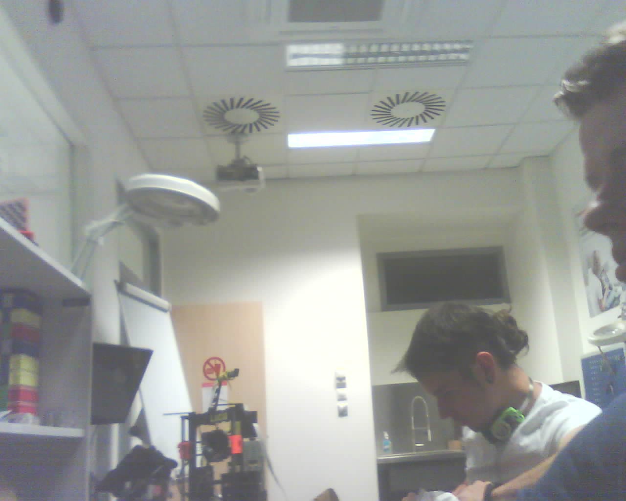
- Camera module - working
Here is our first picture which we grabbed by this board (Luboš is that nose and eyes at right side).
For now all parts of the board are working. I can use all of the boars which I have if I will repair my faults. One of them is that shared pin. We found out that, if we stream pictures from board and we try to use light sensor in same time, picture will be broken. Another problem, the major one is flipped connection to the FPC connector. Because I used connector library for Eagle from someone on the Internet and I did not checked where pin 1 is and where it should be, I routed all my connections for FPC connector wrongly.
All of these mistakes will be repaired in revision B of the board.
At least, here are pictures of assembled board in 3D printed holder (camera module is intentionally backwards).


Discussions
Become a Hackaday.io Member
Create an account to leave a comment. Already have an account? Log In.