 Gabriel D'Espindula
Current status
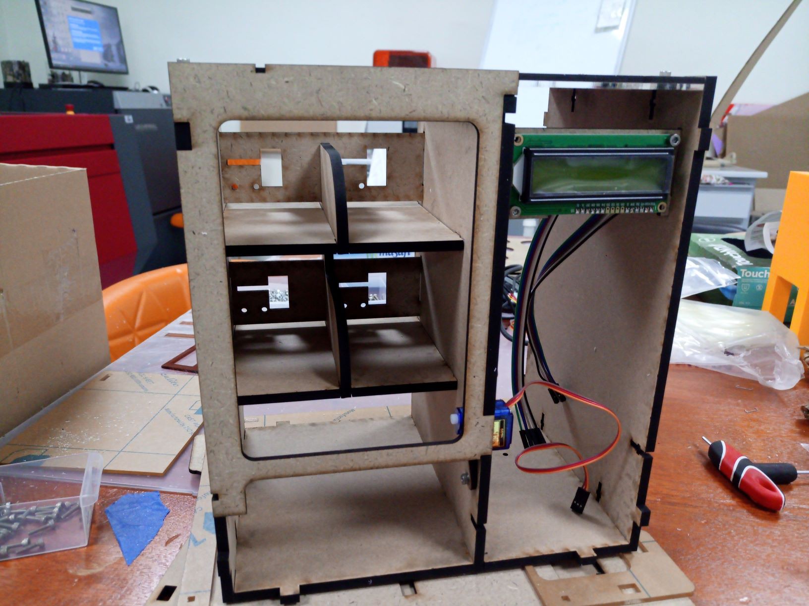
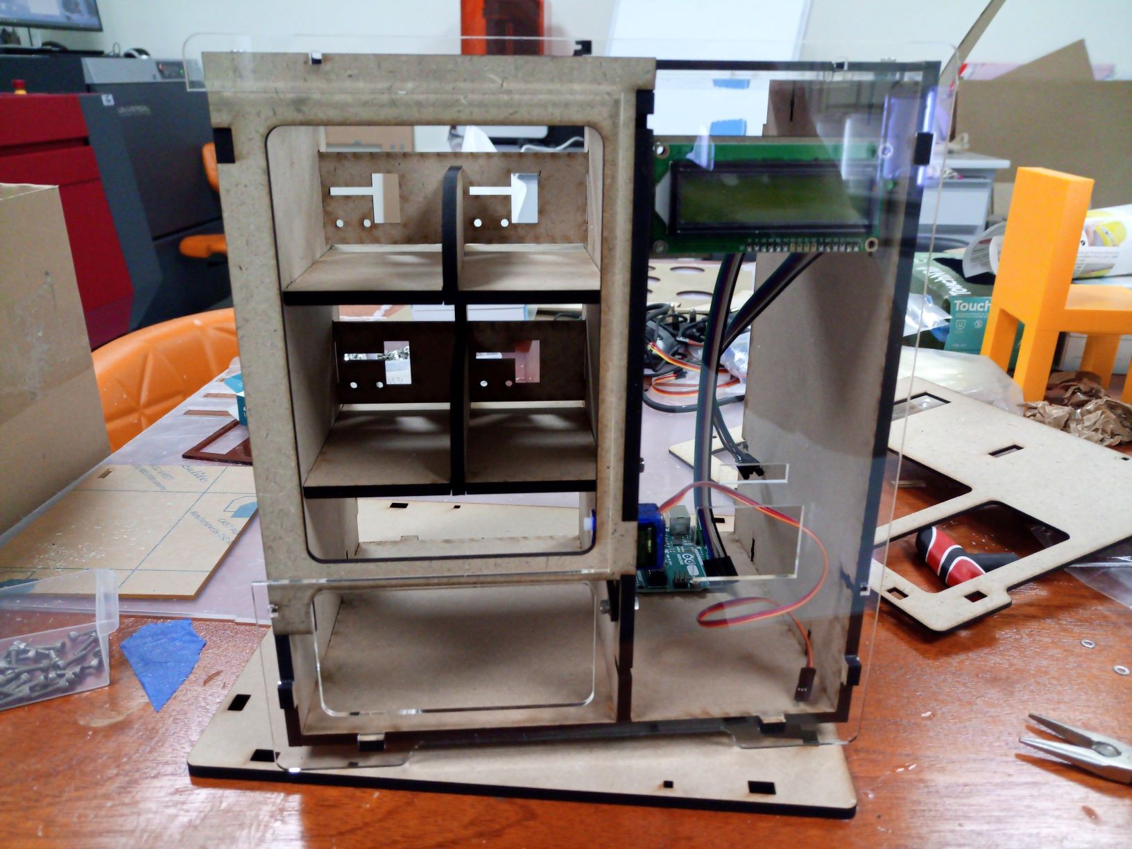
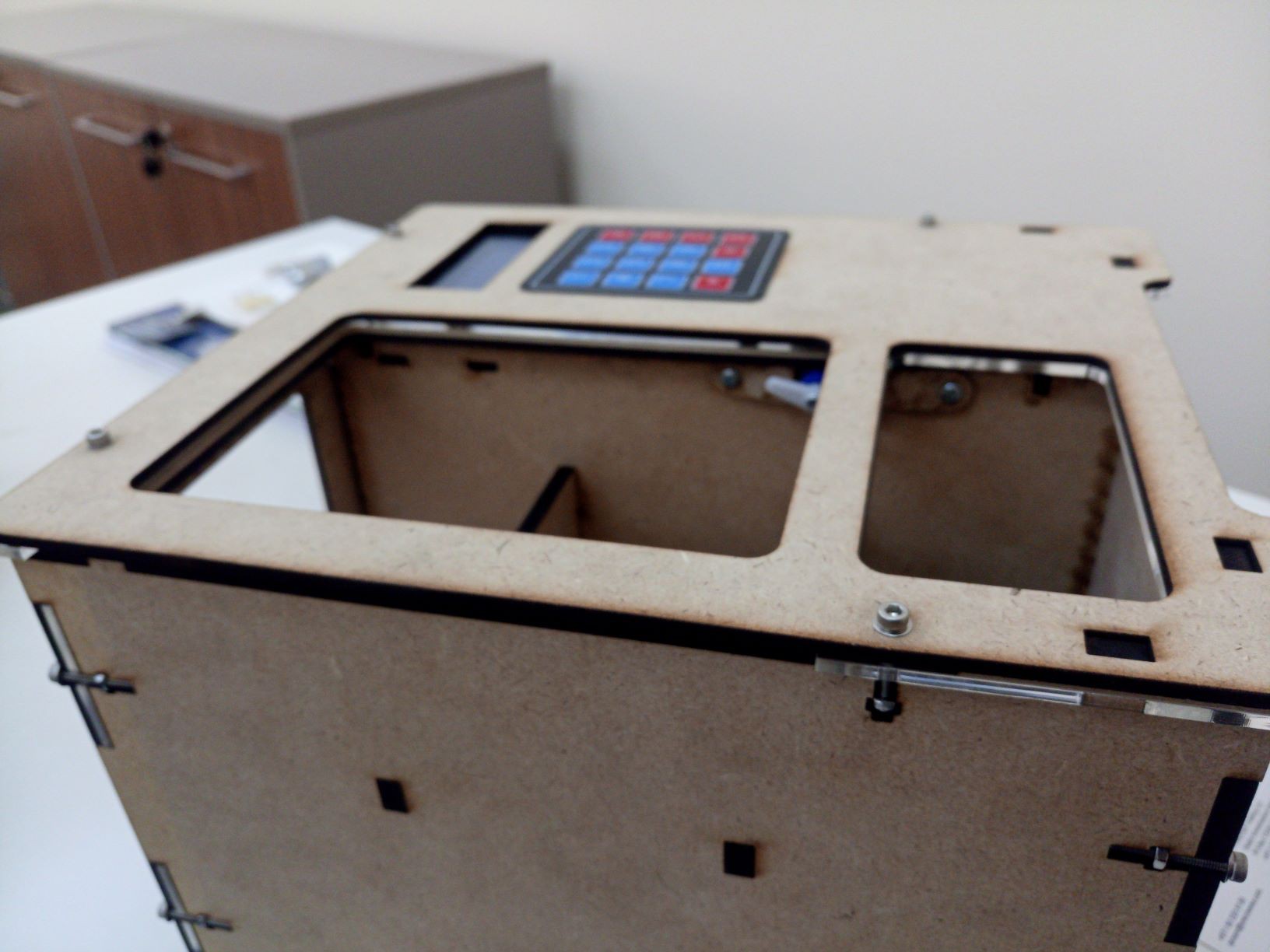
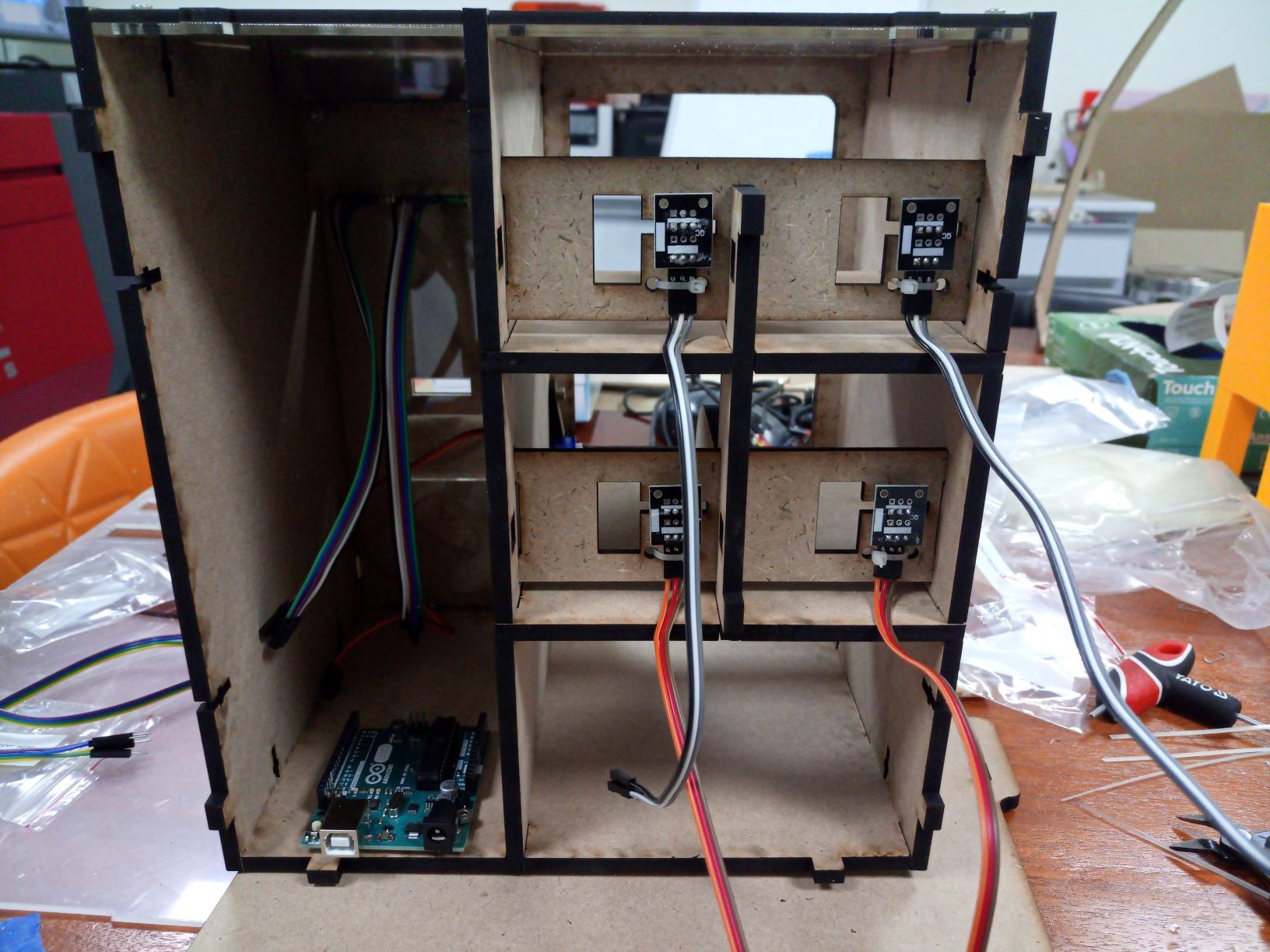
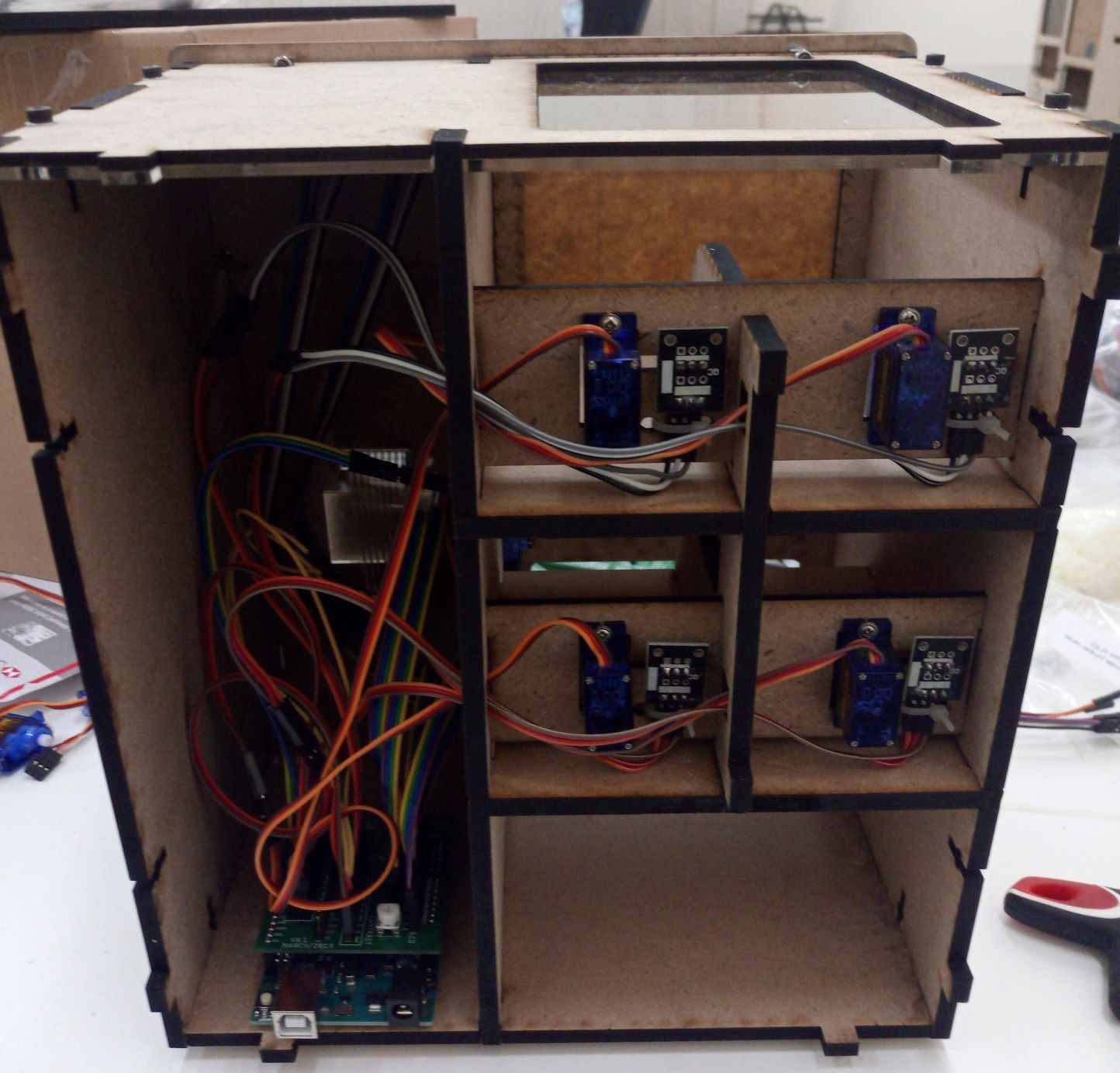
Currently I have a full offline working version as following:
I'll start briefing what is the status of this project and later will explain step by step how I designed and how can you replicate it, just don't forget to mention this page as reference!
If you agree with some improvement point and want to cooperate, just send me a message.
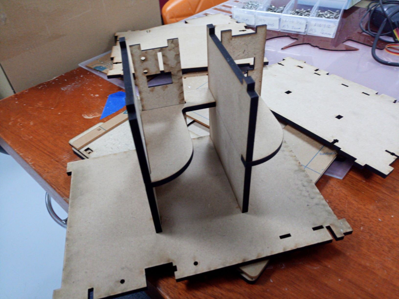
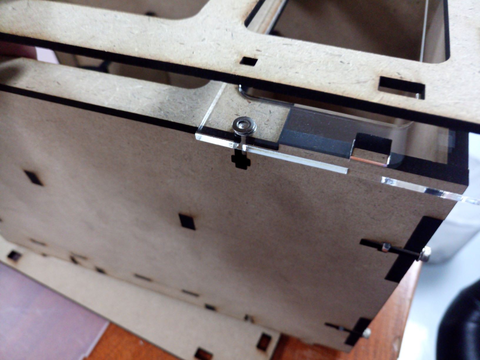
Mechanical design:
- Fusion 360 project is stable and works, but doesn't have any assembly, only 2d project;
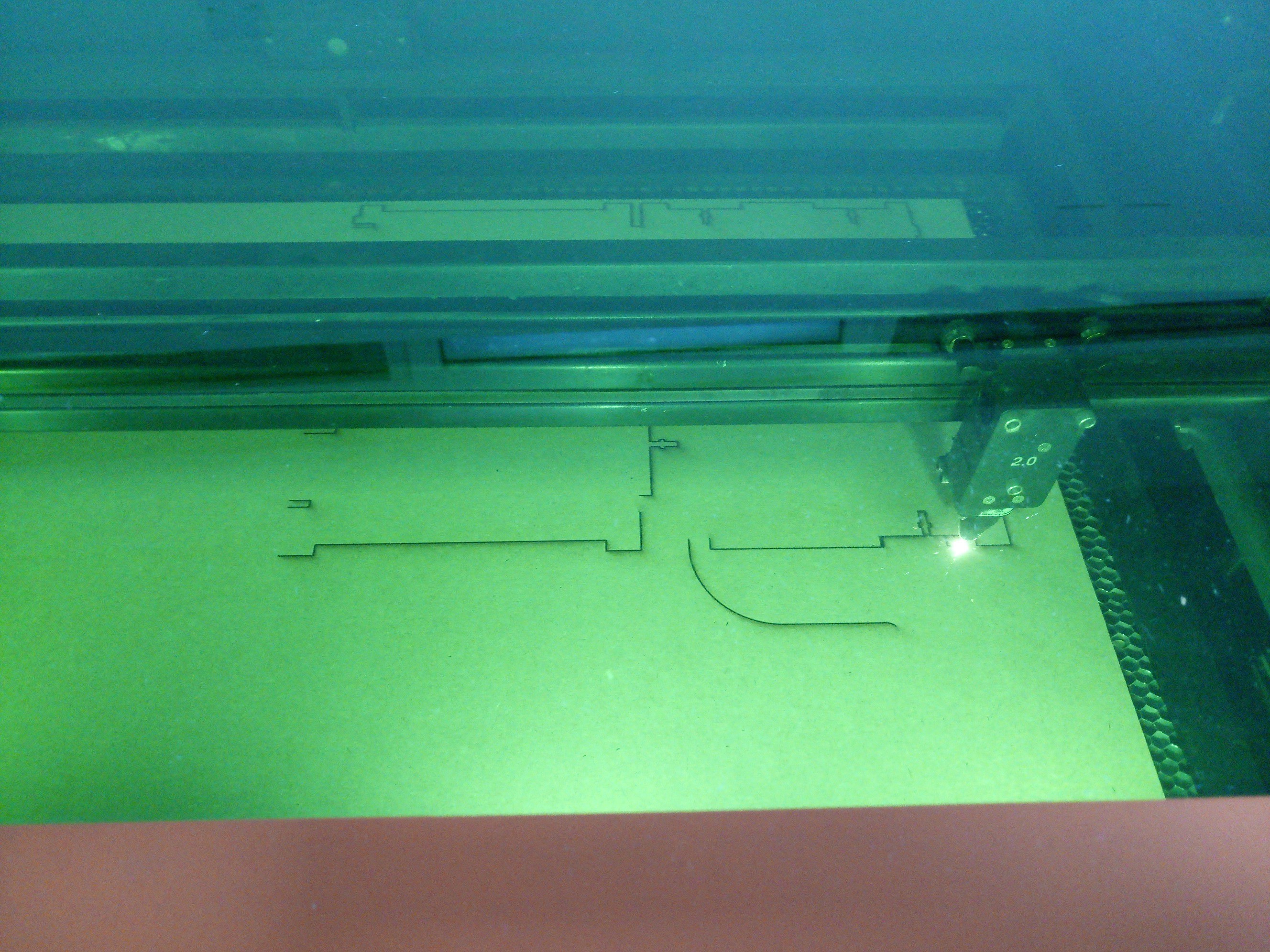
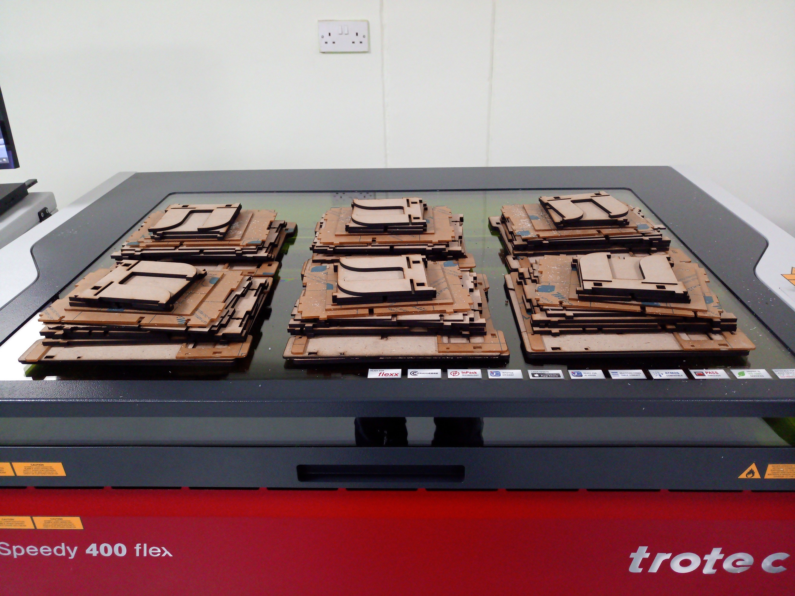
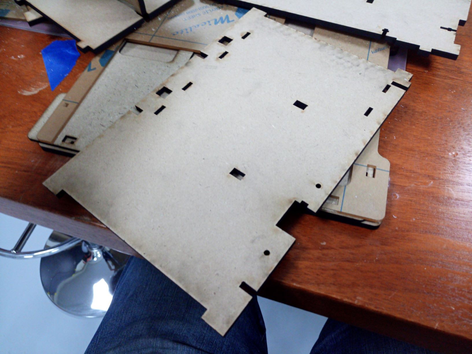
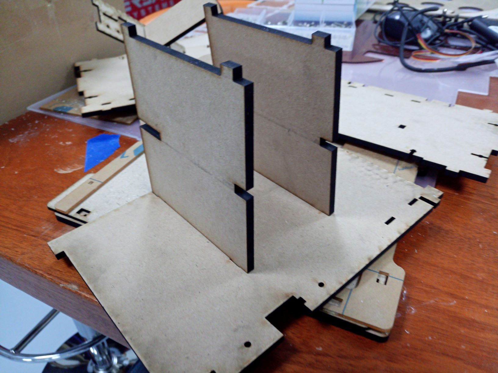
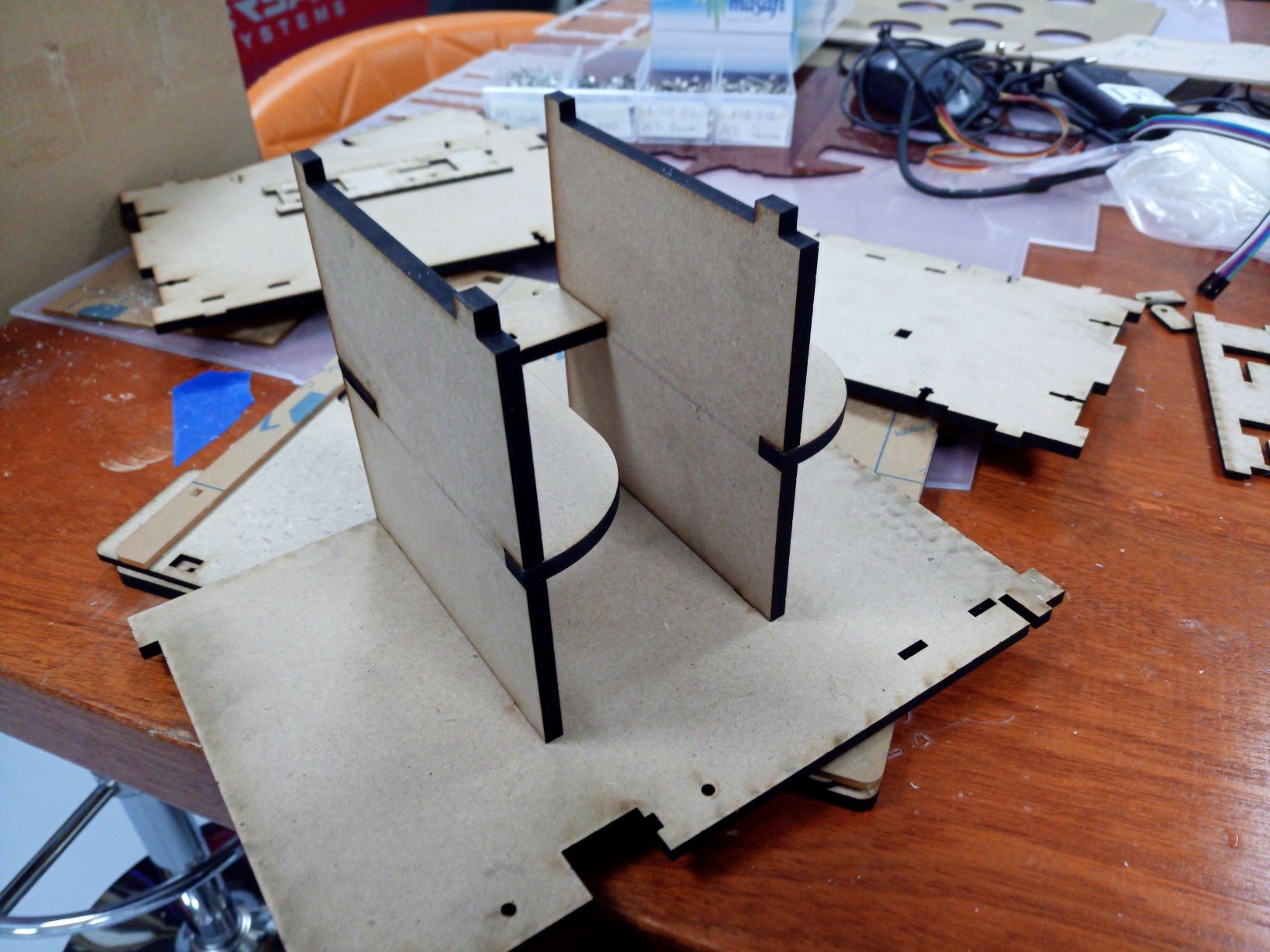
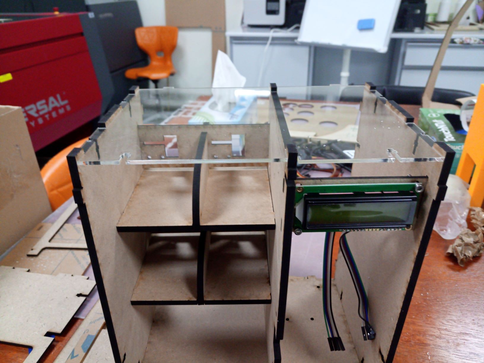
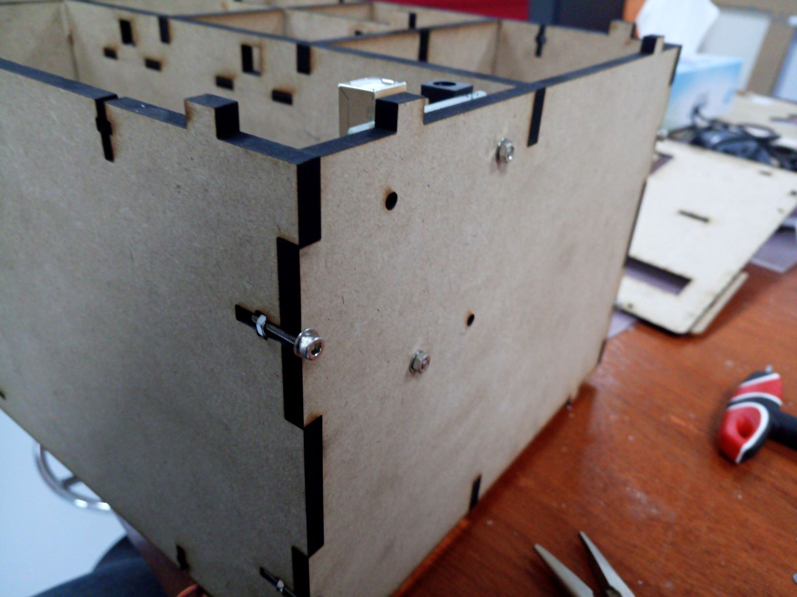
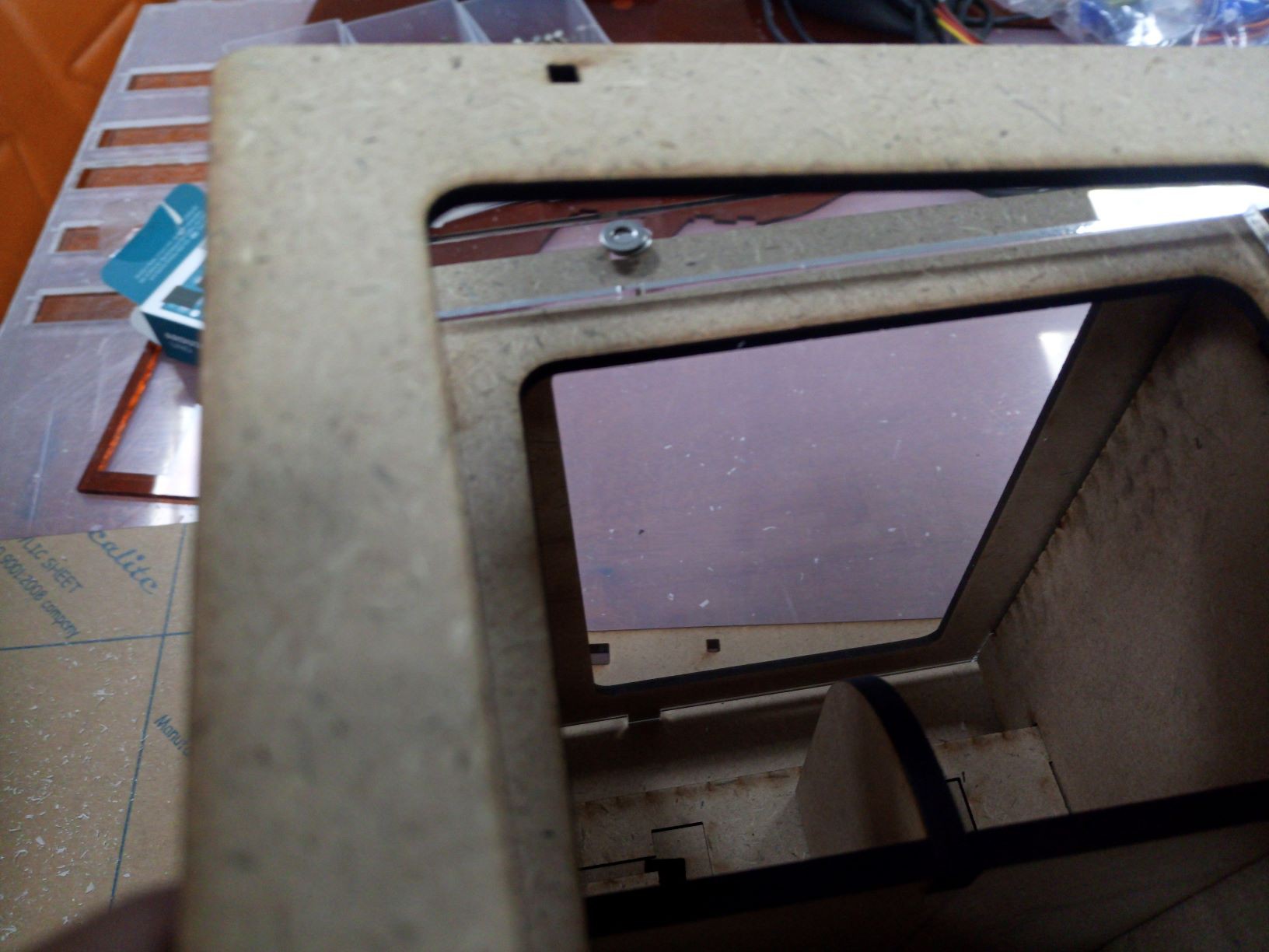
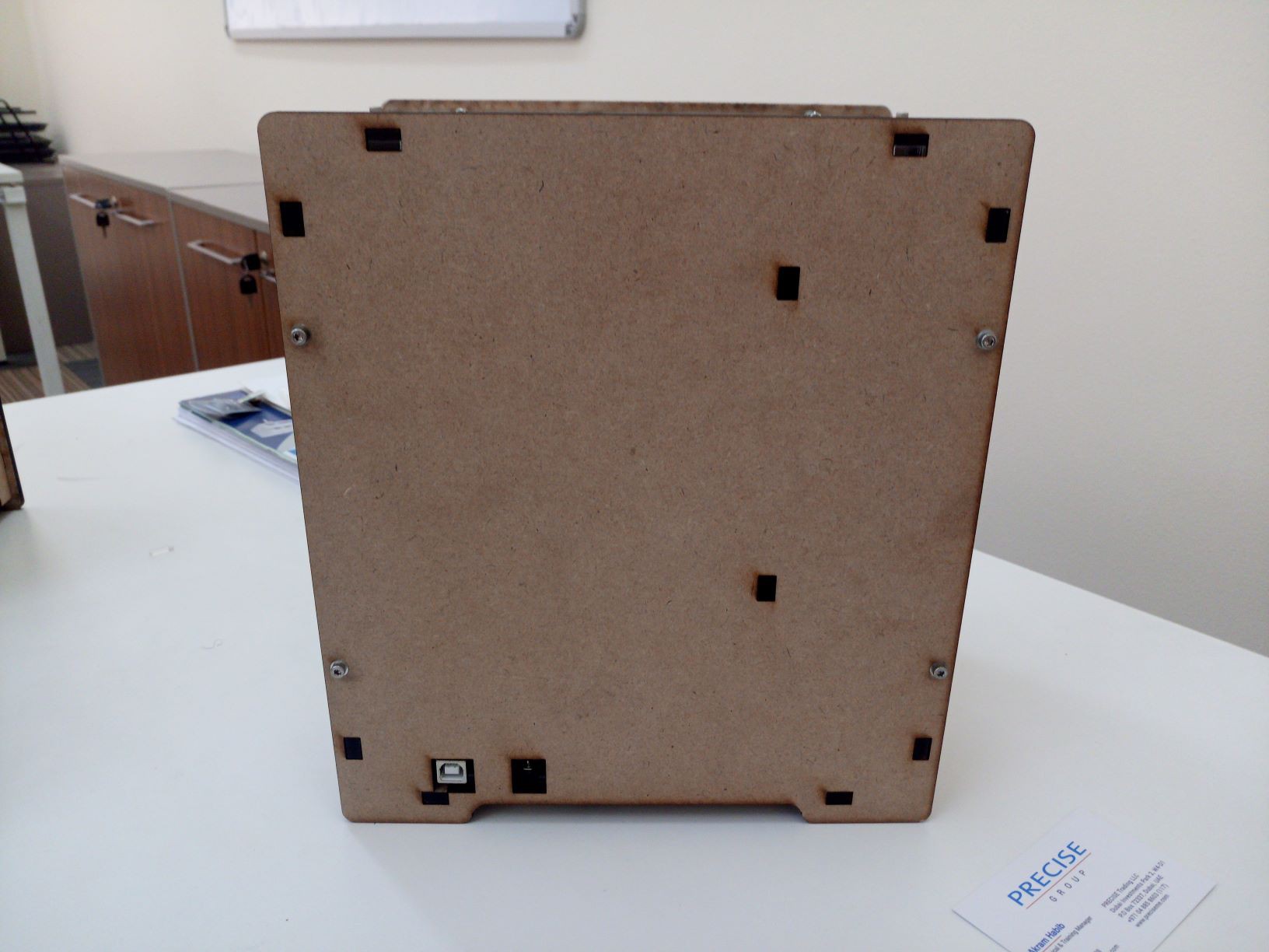
- Second version cut on laser, has a sliding door that can be locked;
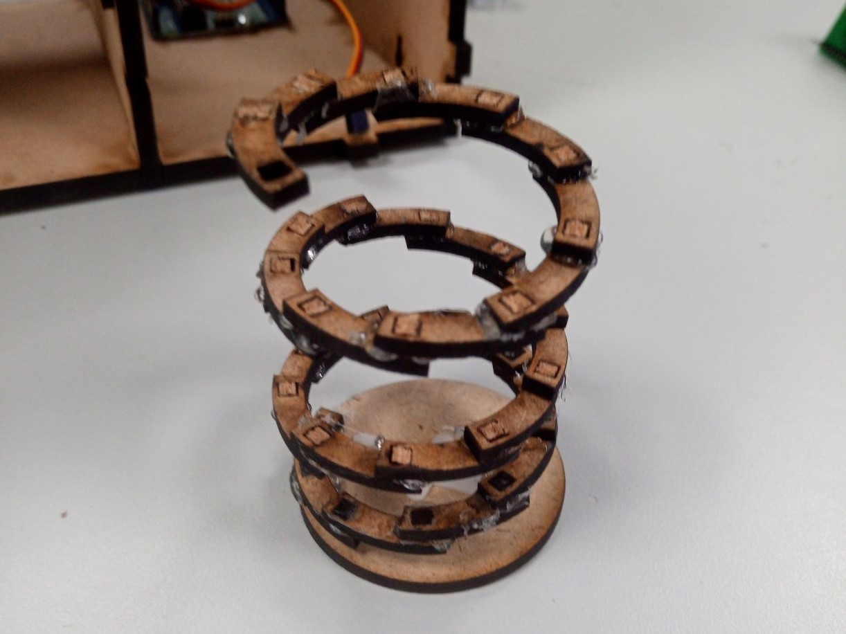
- Didn't find a reliable solution to the delivery spring;
- Improvement points:
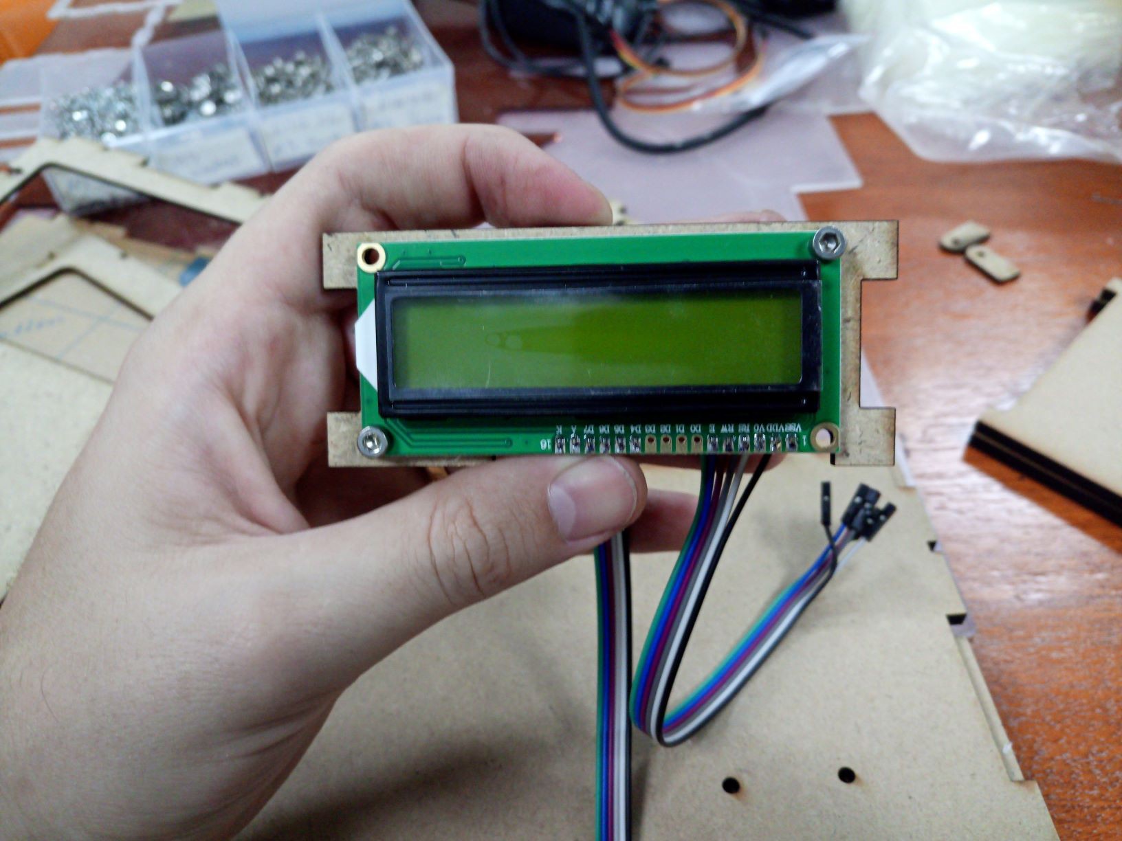
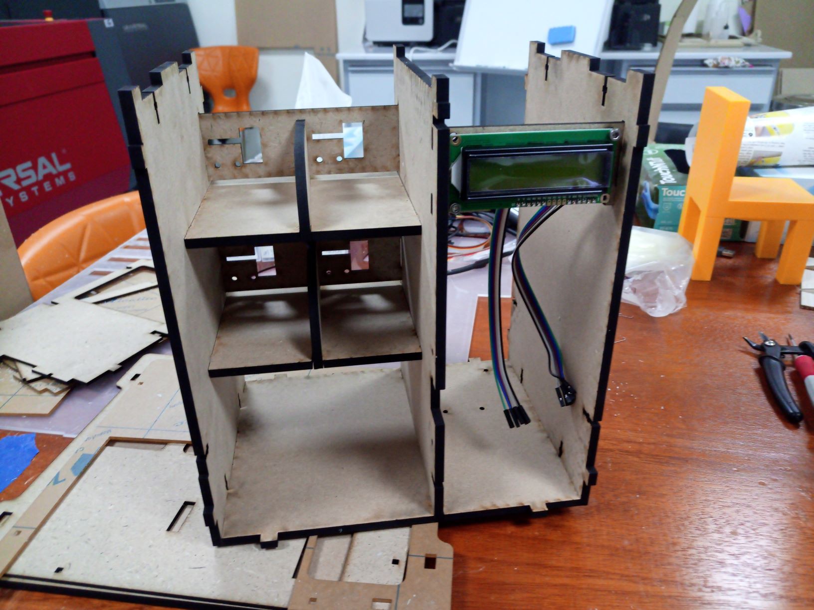
- Match Arduino connector cuts, currently they are a bit decentralized and big;
- Center display, so far it's decentralized and it freaks me out;
- Finish 3d design;
- Automatically change the project creating all mechanics (3d and dxf) based on the following parameters:
- n rows of product cells;
- n columns of product cells;
- n products per cell;
- payment method (coin, rfid, login/password);
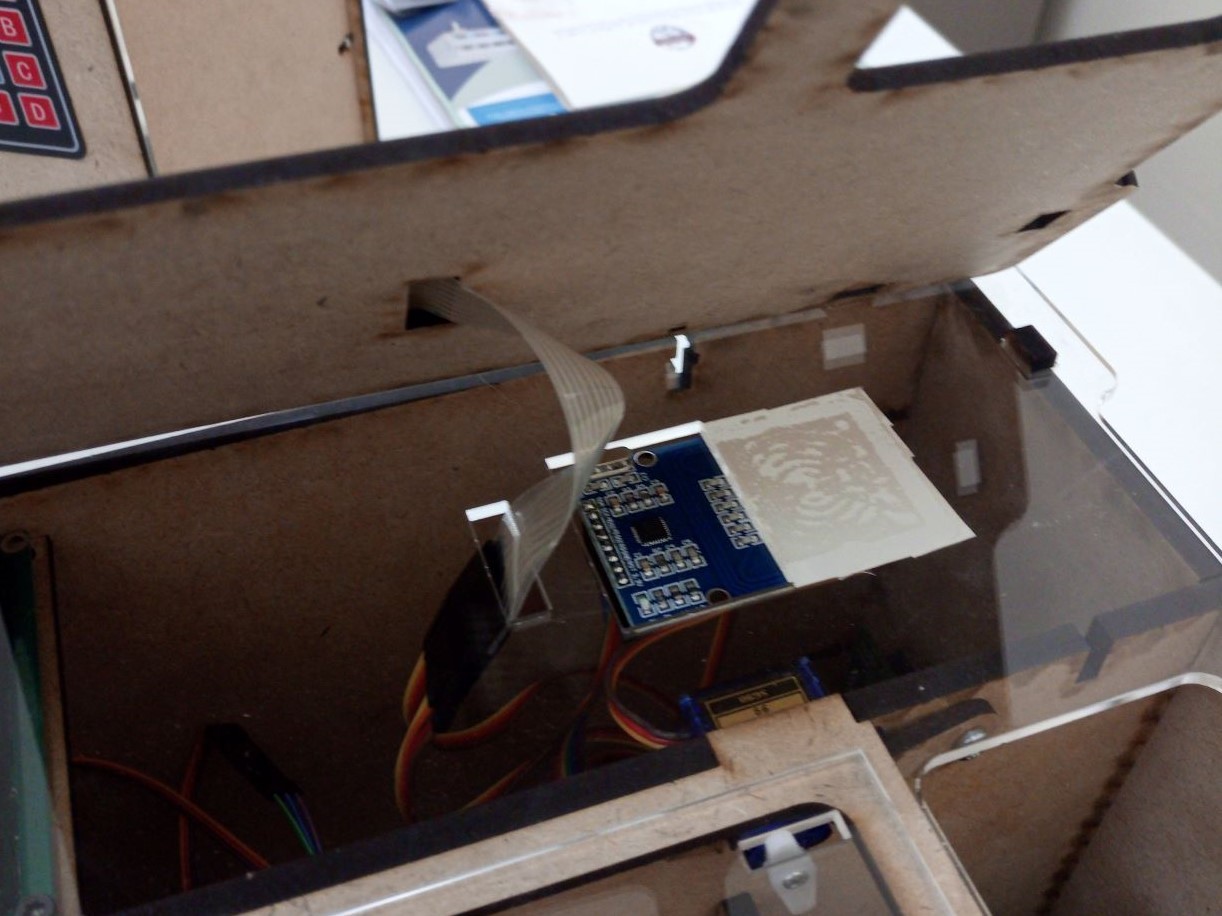
Electronics hardware design:
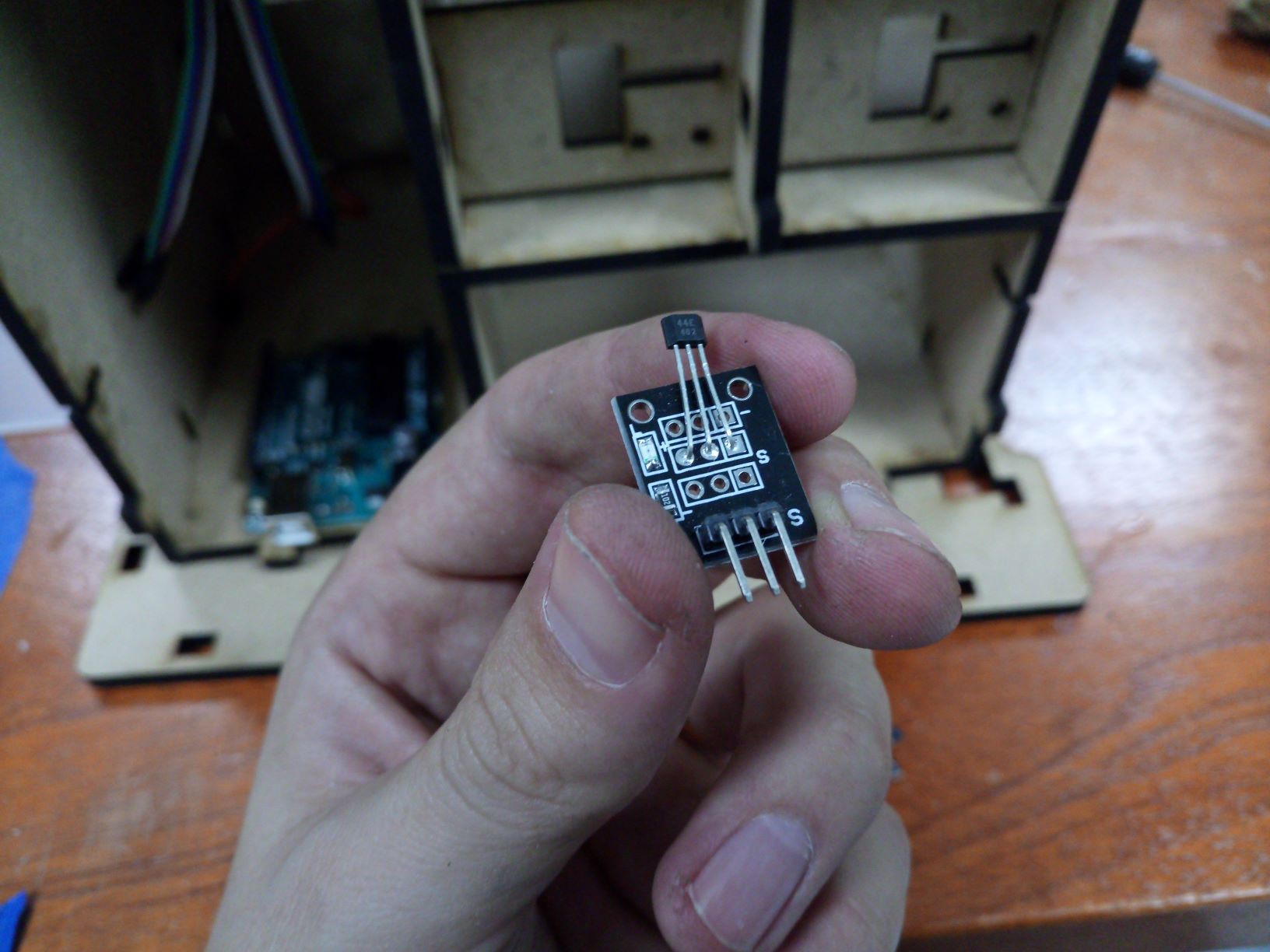
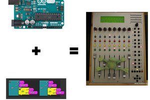
- Shield designed compatible to Arduino and WordSkills STM32L board, both work;
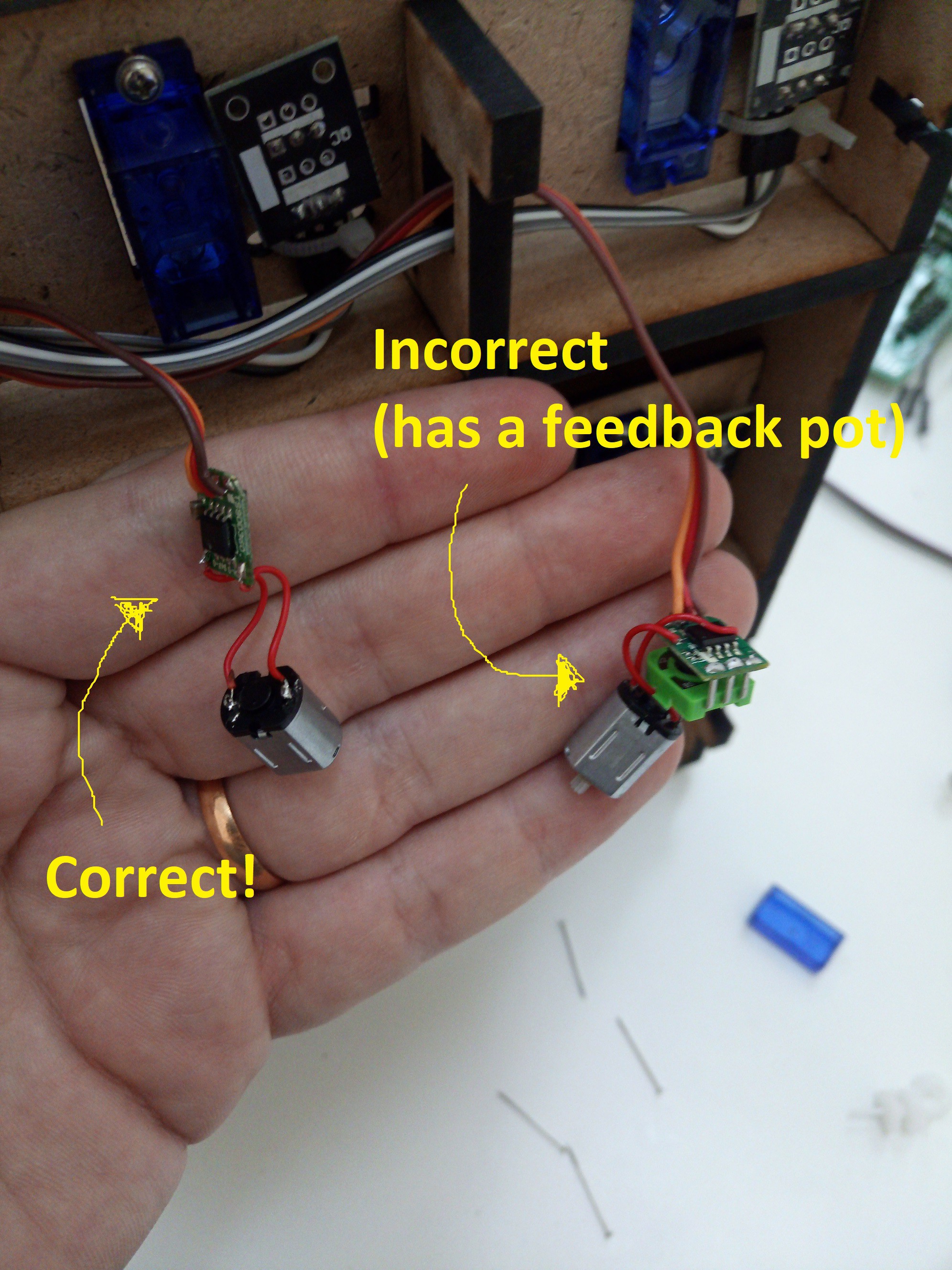
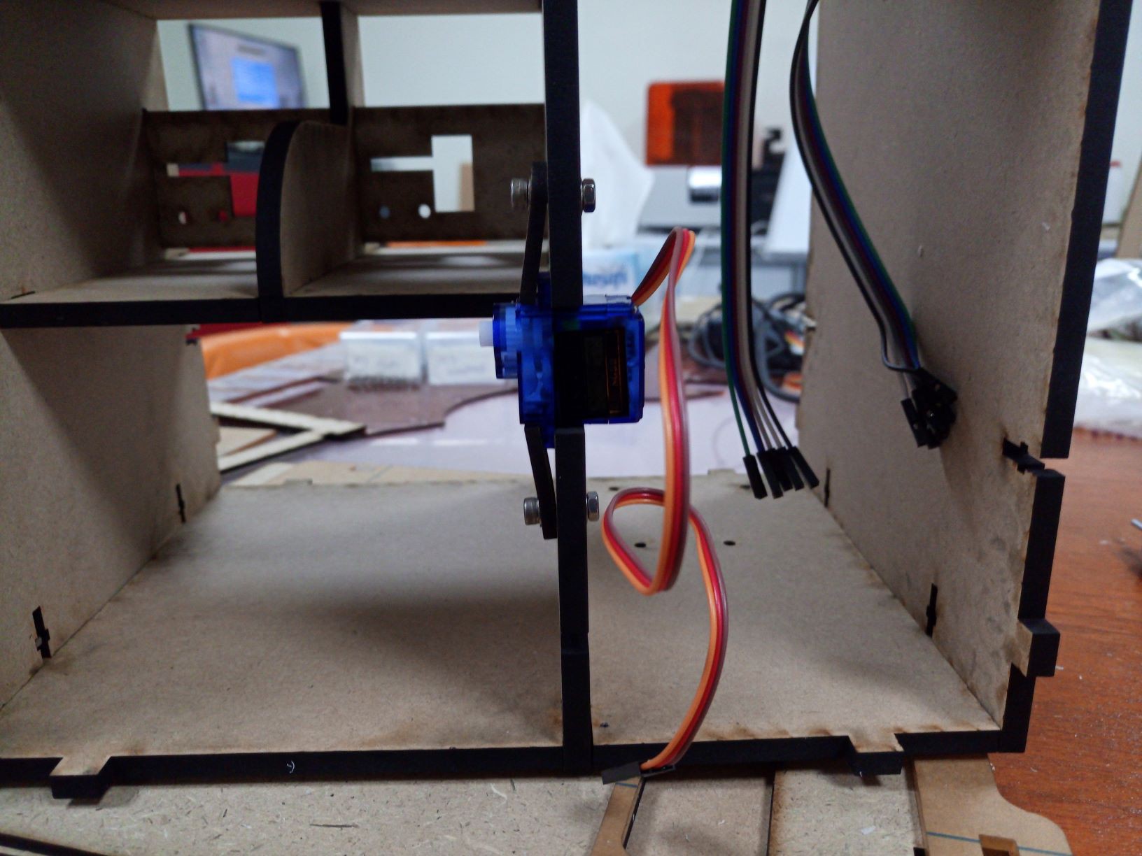
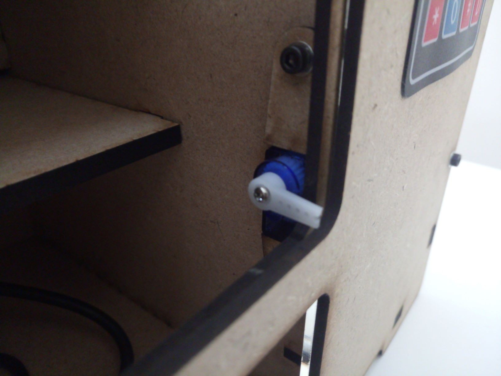
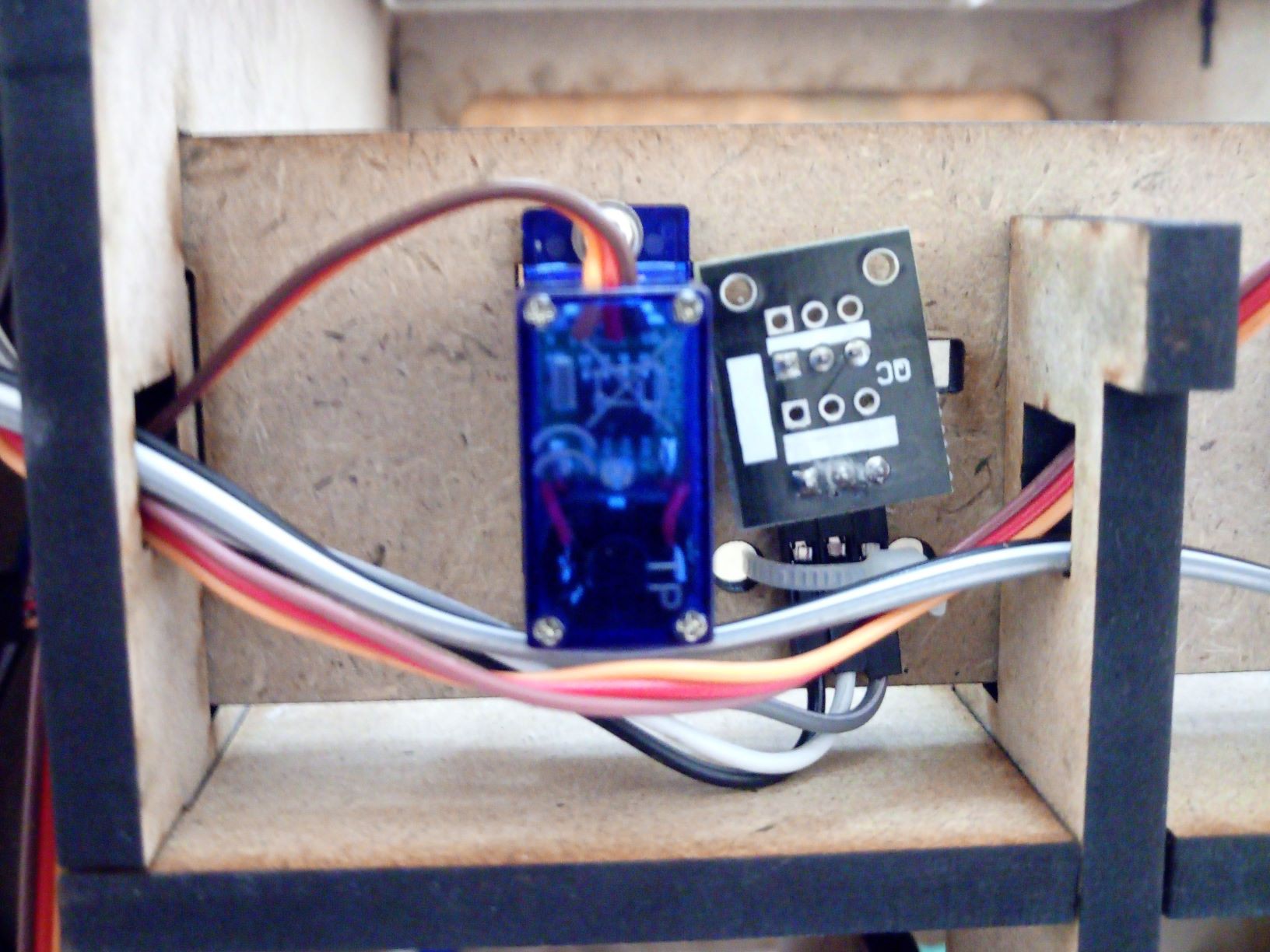
- Be careful with the continuous rotation motors! At the detailed description session there is a better explanation;
- Improvement points:
- Would be way better if the motor were i2c (or any other addressed communication), specially if this project escalate to a parametric design. Currently there are no available pins and a parametric design would increase the number of necessary motors;
- Shield isn't compatible to a coins reader;
- There are no available pins to control the LEDs;
- Add some network to access a web database, W5100 or ESP;
Embedded software design:
- So far the basic offline system works fine in Arduino. I'll release the complete solution as soon as I finish it. The issue with continuous motor were unexpected and I spend more time than I wanted to solve it;
- I didn't have time to finish the STM32 version code;
Alright, now let's finally start!
Introduction
I made a small research and found a couple vending machine projects:
- https://blog.arduino.cc/2016/06/29/venduino-is-a-diy-arduino-vending-machine/
- https://howtomechatronics.com/projects/diy-vending-machine-arduino-based-mechatronics-project/
I really enjoyed the first project proportions, but didn't like the number of bolts and internal electronics/cabling. The second one is really better for escalating in size, but I was looking for something simpler, more similar to the first option (the one isn't fully open source).
At the end my decision was to start from scratch and I came up with the following features list:
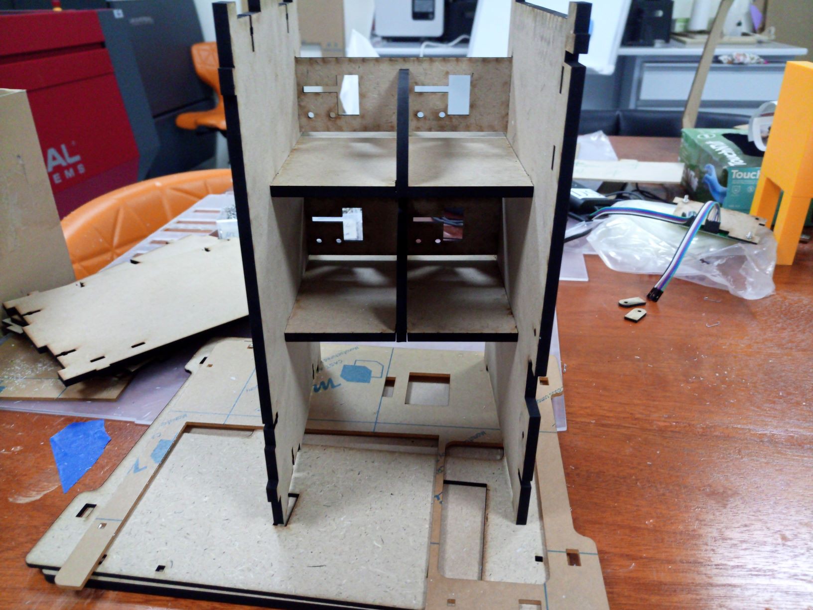
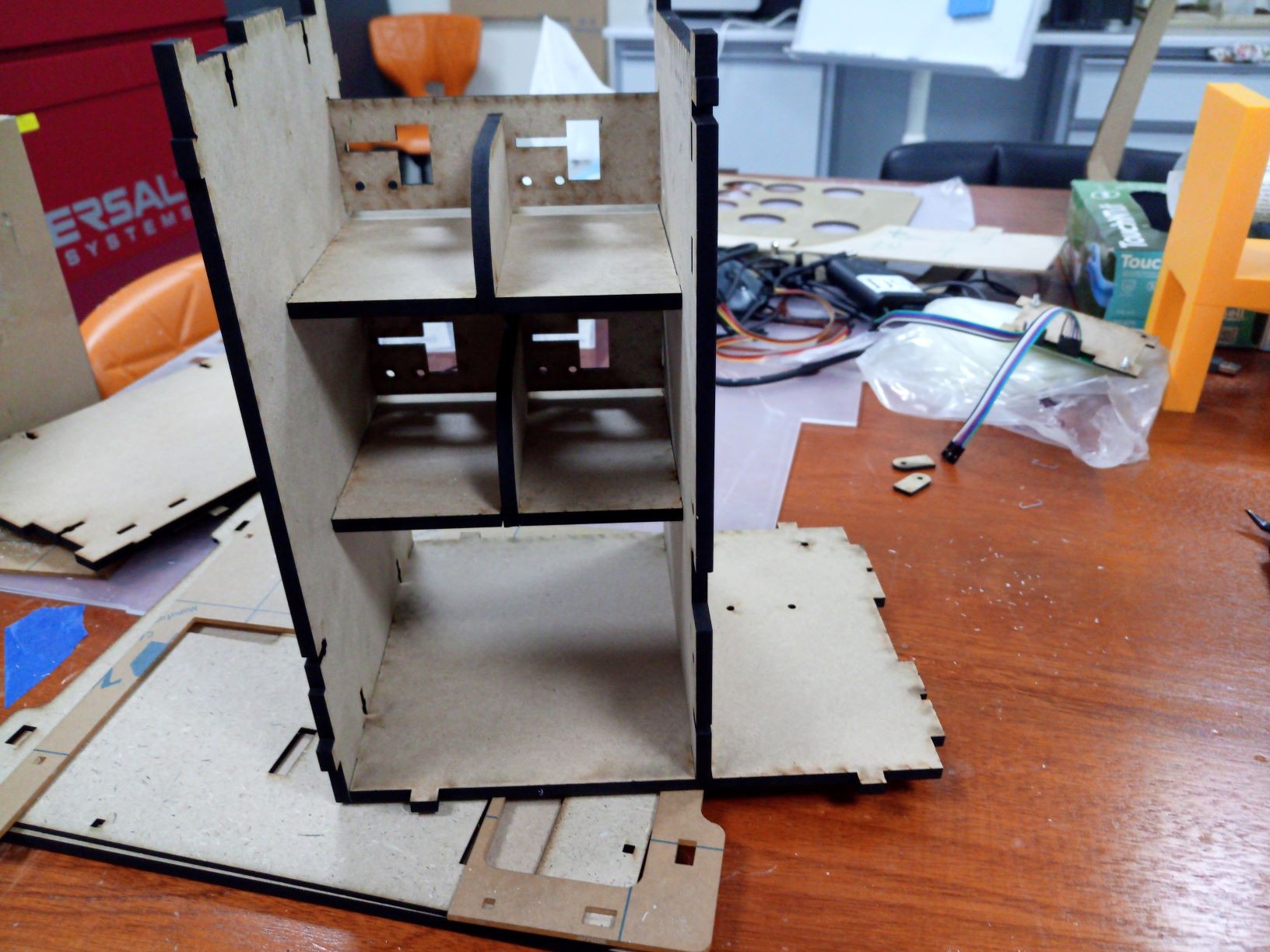
- Small size;
- 2 rows by 2 columns and 3 products per cell, every product allocated in 3cm threads;
- No motor apparent from outside;
- A "lockable" front door;
- Arduino uno and WorldSkills STM32L boards compatible;
- Login/password to "buy"
- RFID to "buy"
- Mechanics reliable and digitally fabricated.
First design decisions
As a first step after deciding the project features, I like to choose which tools I'll use to design. Usually for those non profitable designs I rather selecting software, devices and technologies that I never used before and want to learn, so if you're specialist in some of those tools and could give me some tips, I'll be glad to hear.
I might update this list in the future (after adding network for instance) but to do stuff as it is now I've used the following:
- Fusion 360 to the mechanics;
- InkScape...


 Alden
Alden
 uri.shani
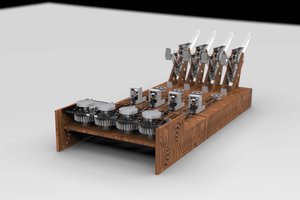
 Jason Cho