 Rodolfo
We started to assemble the infrared relative location circuits but it took us more than hours for the first two pieces. We spent other four hours to test their functions, finding many issues that were conflicting with the design. It was critical to our success that our previous test of the IR location was rigorous (with all the data shown in our research paper) and that we were able to reconfirm the working circuit re-assembling the original prototype. Our next steps move towards a redesign of the circuit to try that modified implementation.
Issue 1: Industrial design
The steps of the original design for the prototype were:
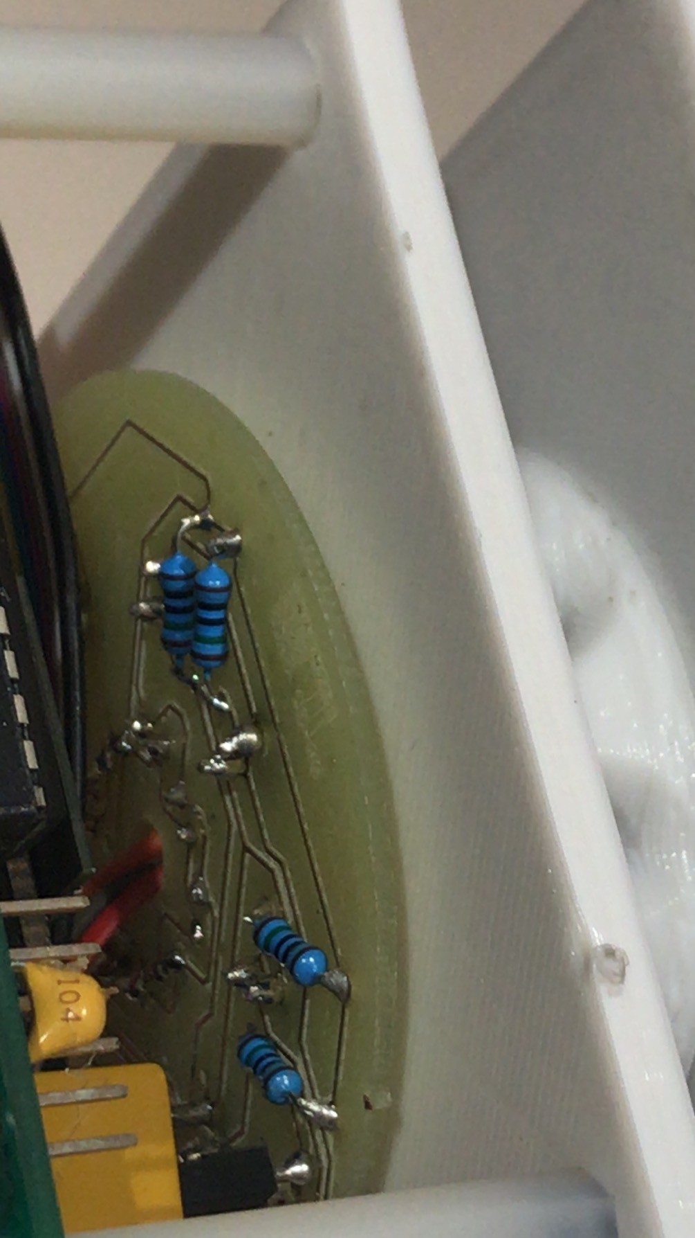
- assemble infrared(IR) receivers, connectors and resistors on the printed circuit board (PCB)
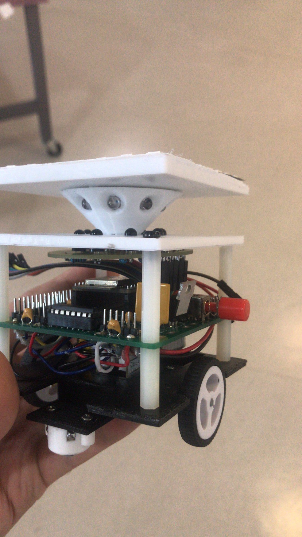
- mount 3D printed base plate
- mount 3D printed reflector cone
- insert 8 emitters (guessing the position of these 16 pins was possible took us 80% of the time)
- solder the 16 pins
- desoldering many of the pins because of guessing their position wrong. Resolder. Solder again.
Issue 2: External capacitors for ADC ultra-low noise pre-amp
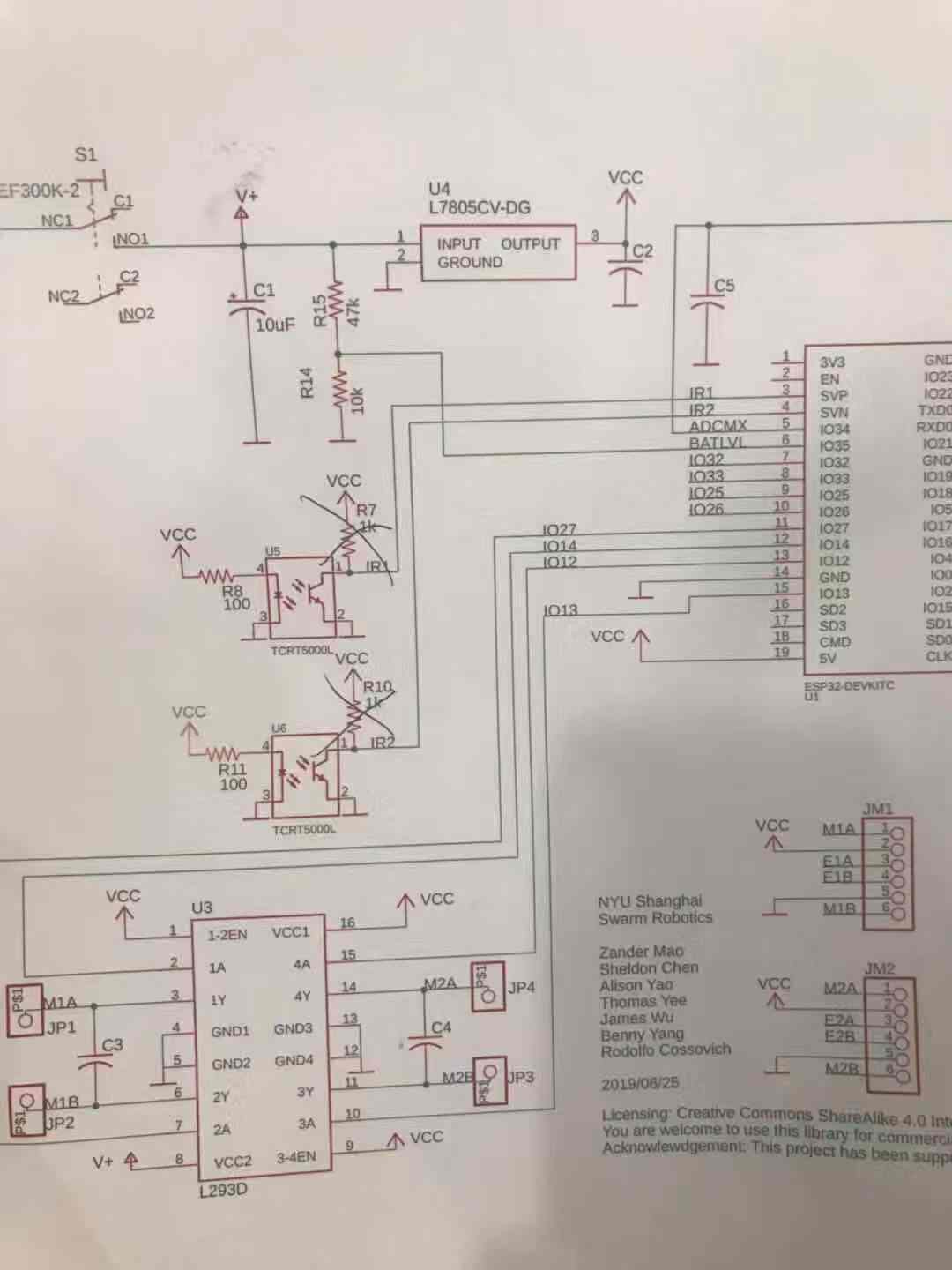
Pins 3 and 4 of the ESP32-DevKitC were in our schematic expected to be used as analog read and to be connected with infrared proximity sensors, hence they had pull-up resistors. After digging about the extra functionalities they have, they have functions related to the pre-amplifier of the analog digital converter. The manufacturer suggests to connect a capacitor of 330pF between these two pins to get ultra low noise.
We didn't try that, but we can make sure we wouldn't be able to use the pull-ups and the ADC functions correctly. We noticed this when there was a mysterious grass noise on the readings (about 20% of full scale!) but as the IR were not even installed, we removed the pull-up resistors and the analog values came back to normal.
Issue 3: Circuit design
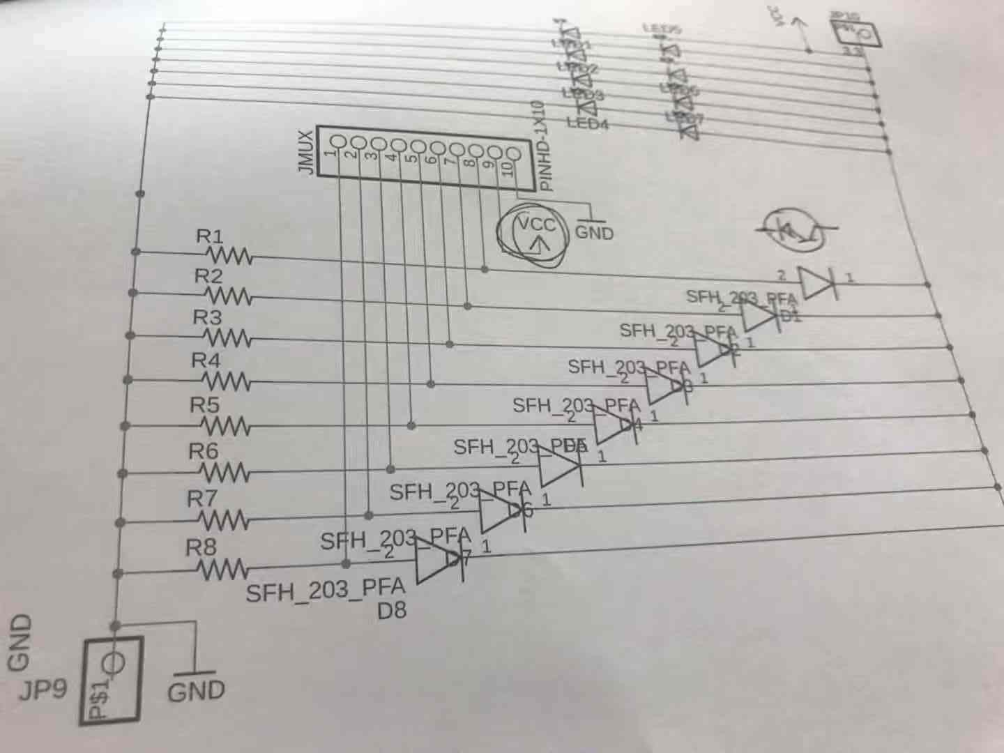
Pin 2 fo JMUX connector was noted as being Vcc on the IR board. But on the main board that pin was coming from a resistor in order to limit the current through the IR transmitters.
Also we had to resolder all receivers because they were noted as phototransistors but they were inverted diodes instead.
Discussions
Become a Hackaday.io Member
Create an account to leave a comment. Already have an account? Log In.