 nh8157
Introduction
After redesigning the cones and plate using Fusion 360, we also used the chip CD4051BE to read analog input from the receivers while using only one analog input pin on Arduino. The IR system worked pretty well on the Arduino mega 2560. However, numerous obstacles were encountered when switching to the ESP 32 platform.
Obstacles
We first encountered the incorrect readings from the receivers. Similar problem were encountered when using the Arduino platform. Back in the last log (Log 3), we thought it was the result of the uneven surface of the cone. With newly printed, conductive-tape-free cones, however, we start to get incorrect readings from the receivers. For example, ideally, when the emitter is pointing at one receiver, two of its neighboring receivers should get the same, yet lower readings. In our case, however, one of the neighboring IR receivers would have reading 1000mV higher than the other receiver.
For an individual receiver, its highest reading may not occur when the emitter is pointing straight at it, but when it is not aligned.
It could be seen from the video, that the peak value, 2700mV doesn't show up when the emitter is pointing straight at the receiver.
A couple of factors were found by us.
- The orientation of the receiver
After twisting the receiver, we found that only when the connection of both pins overlaps the radius of the circle of the plate, the reading would be even from both sides
2. The tightness of the connection between the pins and the wire.
The readings would be really low when the connection is not tight.
3. Environmental interference
Apart from sunlight, the readings would also be influenced when reflective material occurs in the light path of the infrared.
We were also troubled by the decay in the signal when the emitter moves away. When the range between the receiver and the emitter is above 30cm, the signal is almost negligible.
Implementation
To address the decay in signal strength, we thought of two approaches.
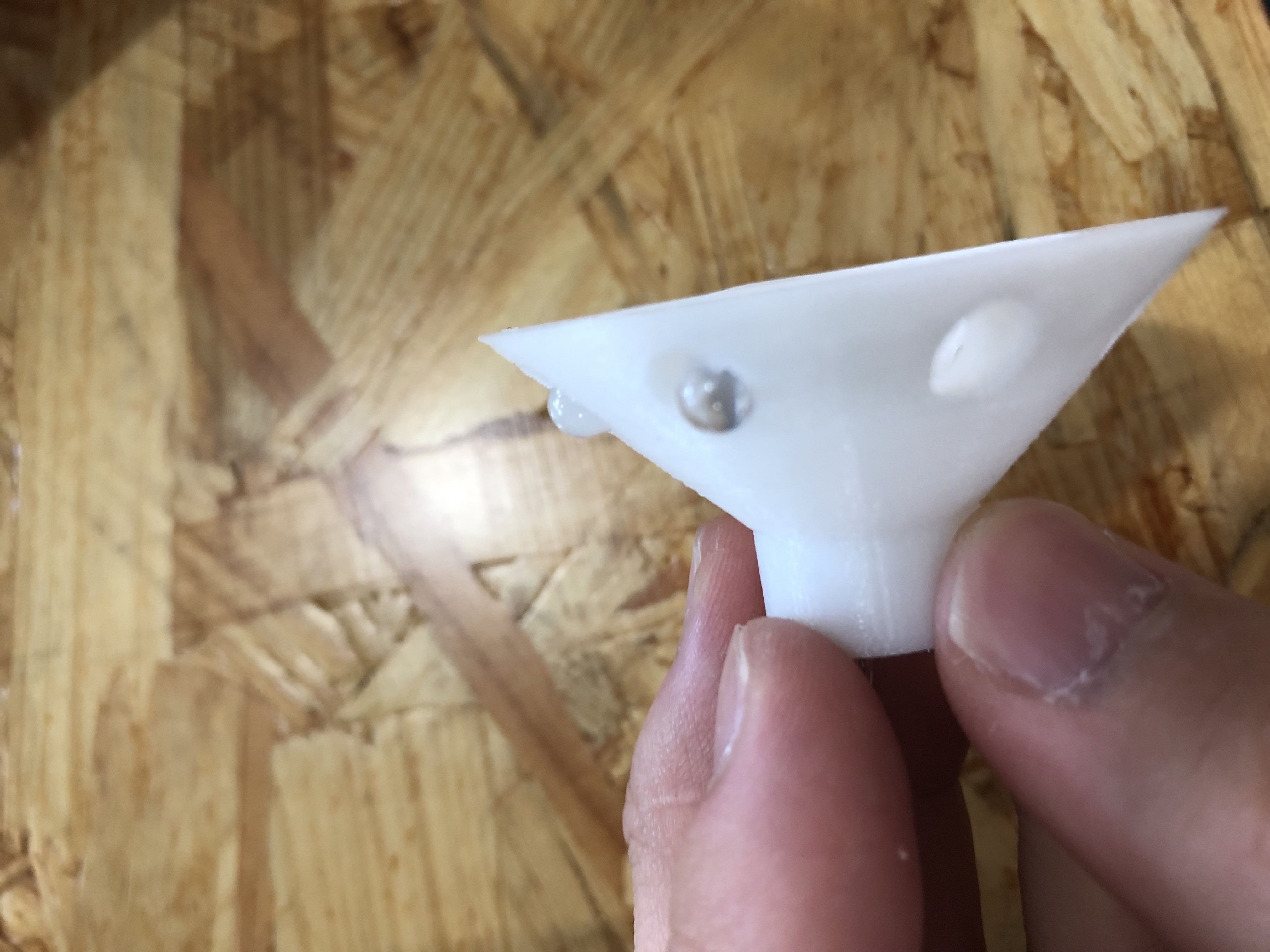
- Apply metal spray on the surface of the cone
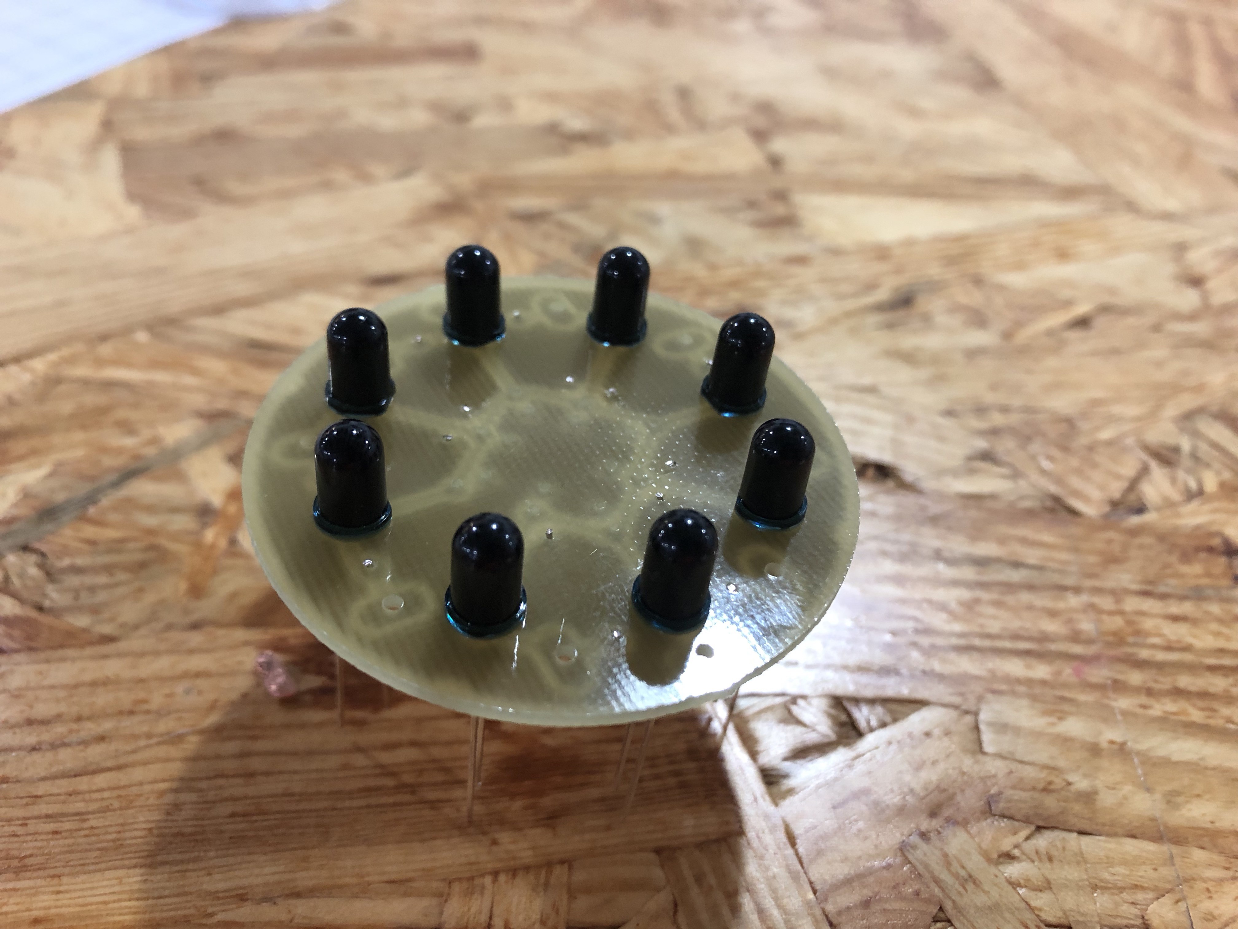
- Let the tip of the IR receivers out of the holes
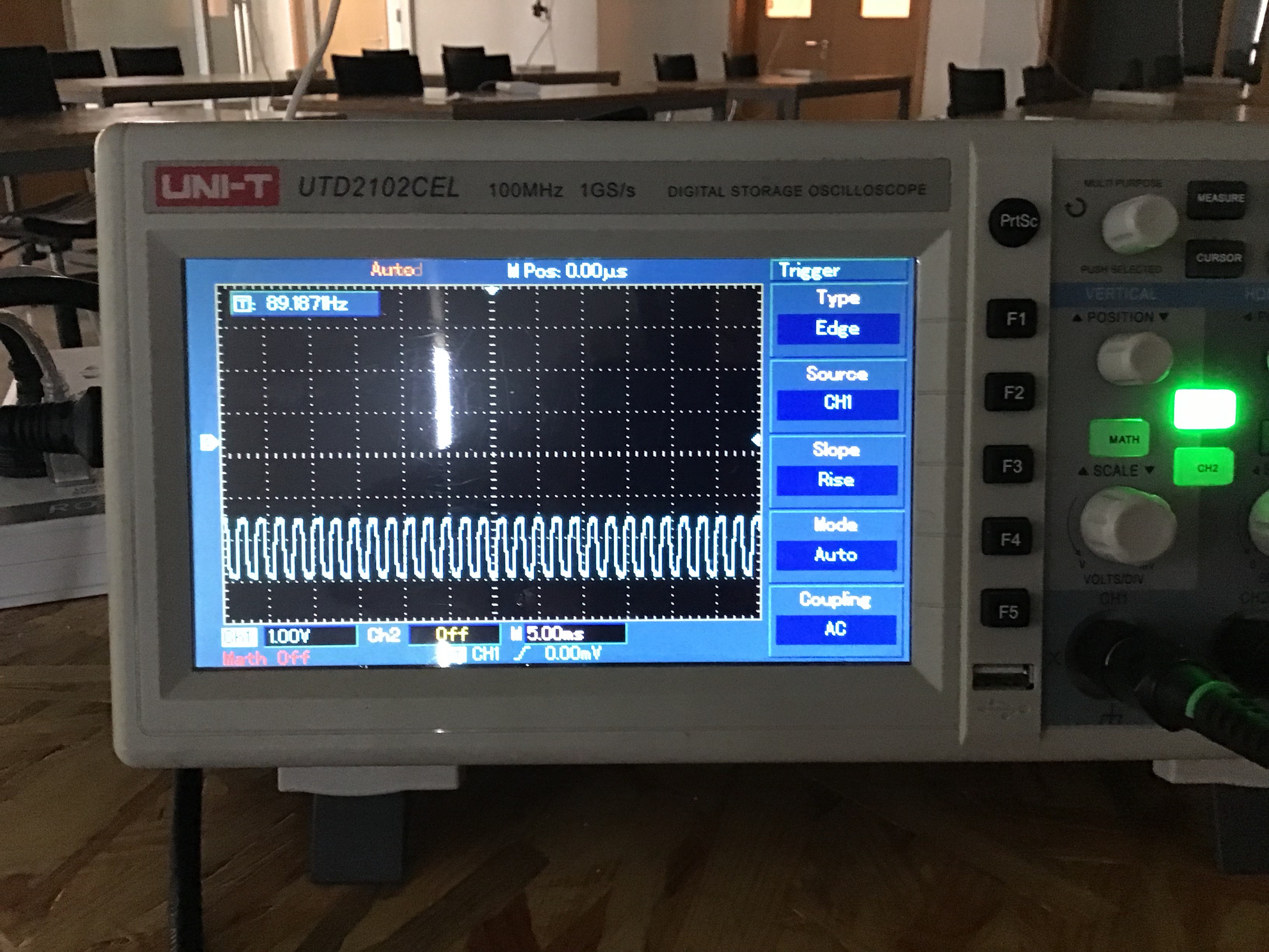
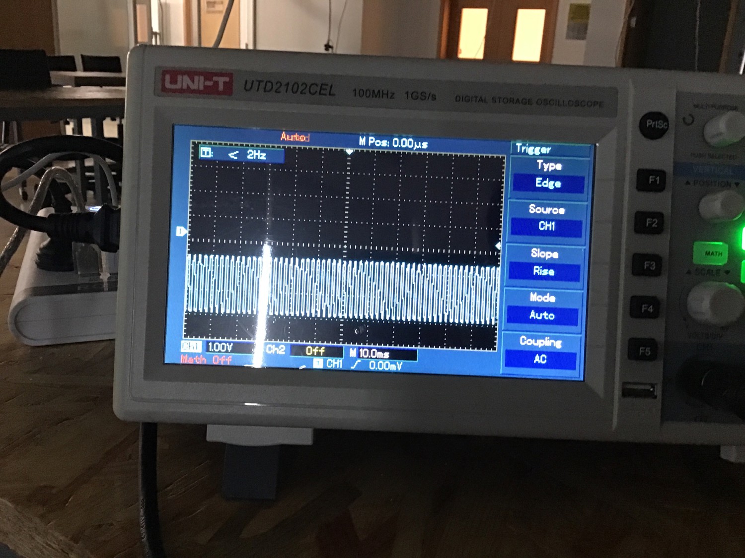
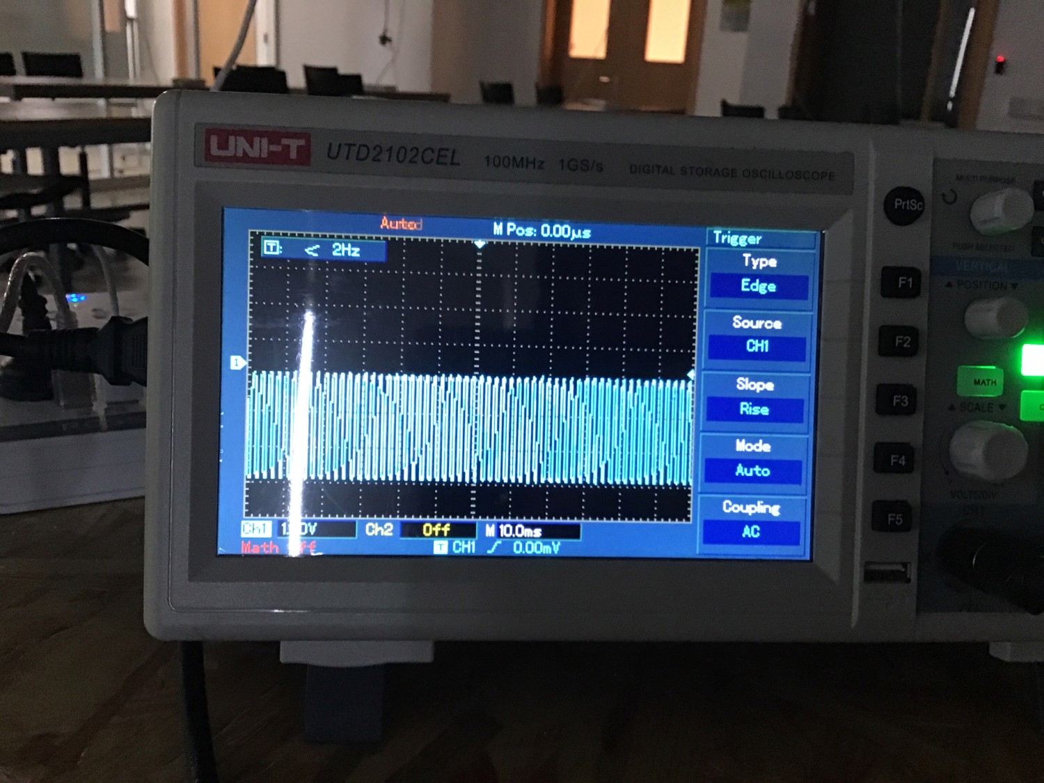
We used the oscilloscope to get accurate results from the receivers.
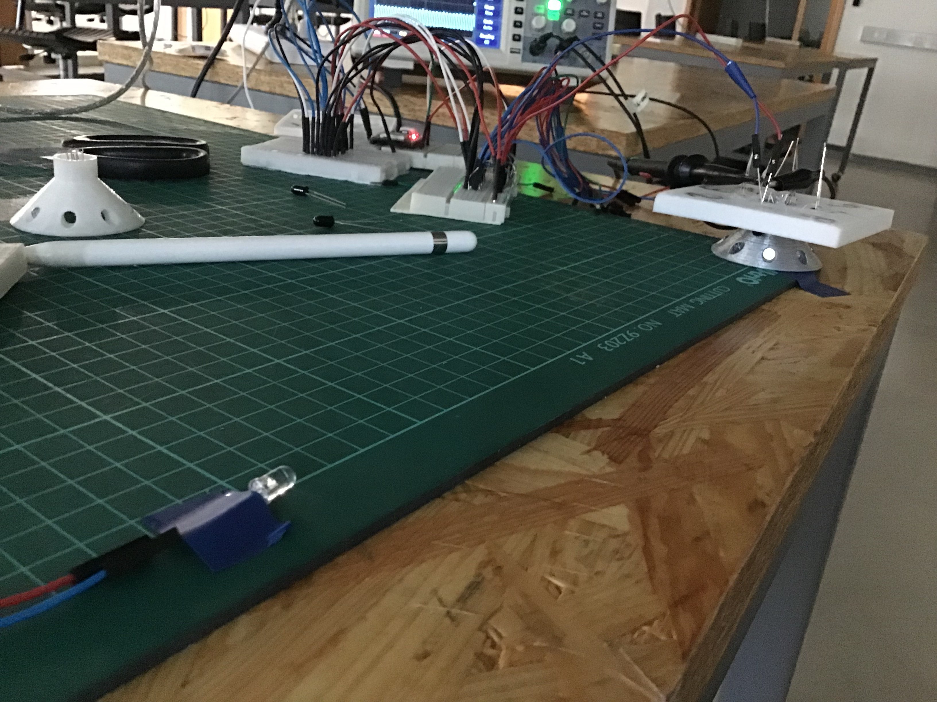

(Cone with spray)
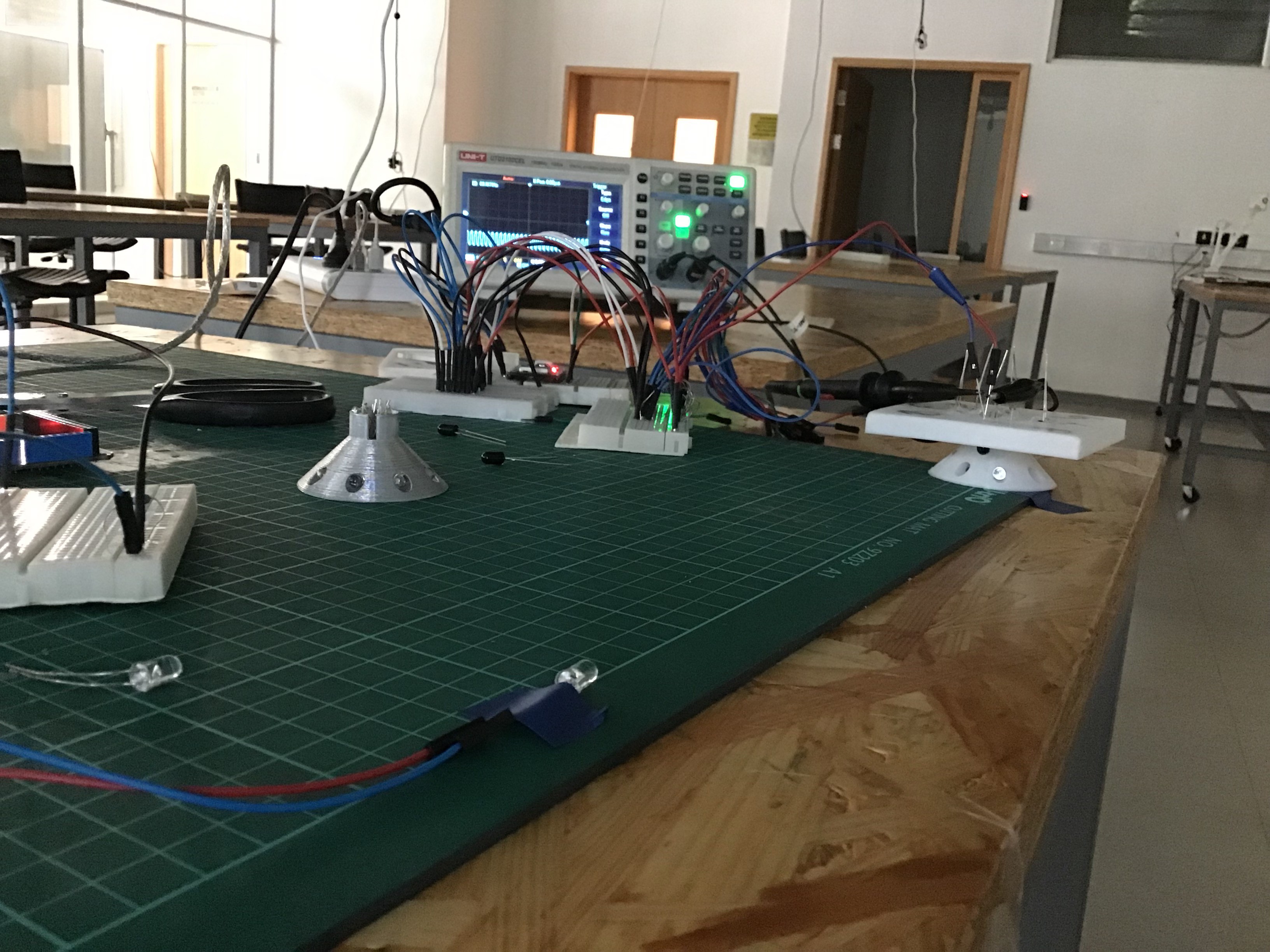
(Cone without spray)
(IR hidden inside)
(IR exposed outside)
We concluded that the best combination would be exposing the receiver outside and not having spray applied to the cone's surface.
To implement this in our design, we shrunk the height of the cone and the plate by 4mm, so that the receivers would be exposed outside.

(New design)
(Original version)
We also tried to let the emitter send infrared signal in a pulse fashion, where the emitter would emit for 1ms and halt for 1ms, waiting for another emission. Though on the oscilloscope, the peak voltage on the receiver is much higher than solely with 3.3V, as we are using the multiplexer to read input from the receiver, it may not be the peak value a receiver receives when the multiplexer is switching to this receiver.
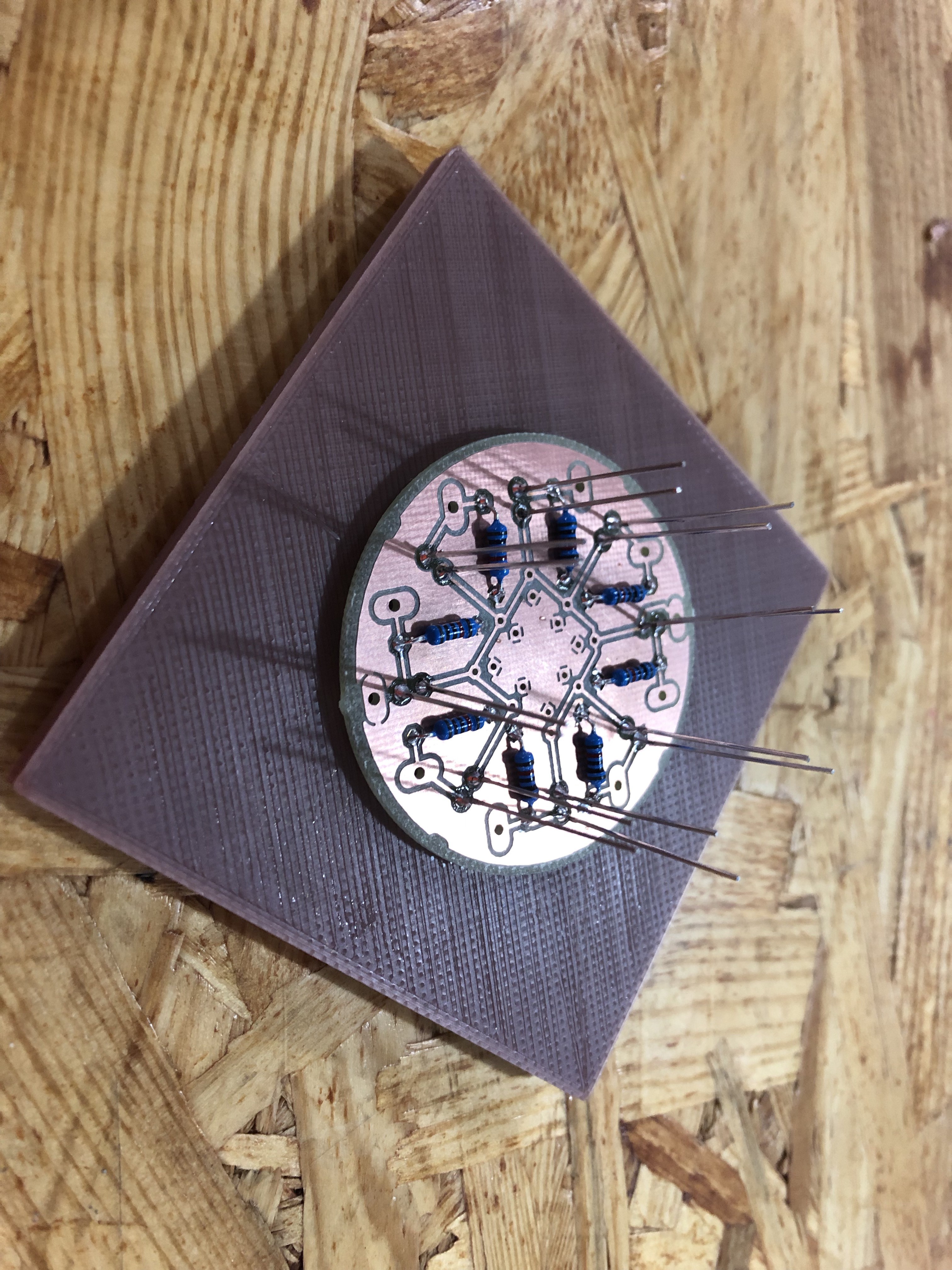
To ensure the connection between the pins and the wire, we designed PCBs and soldered the pins directly to the PCB.
Discussions
Become a Hackaday.io Member
Create an account to leave a comment. Already have an account? Log In.