 nh8157
It's been half a year since we last updated the entry. Recently we talked again about our direction and progress. We realized to make Swarmesh a candidate for distributed system research, we first need to develop a platform with all functionalities integrated and readily available
Necessary improvements to be made on the system are listed below.
1. Positioning system
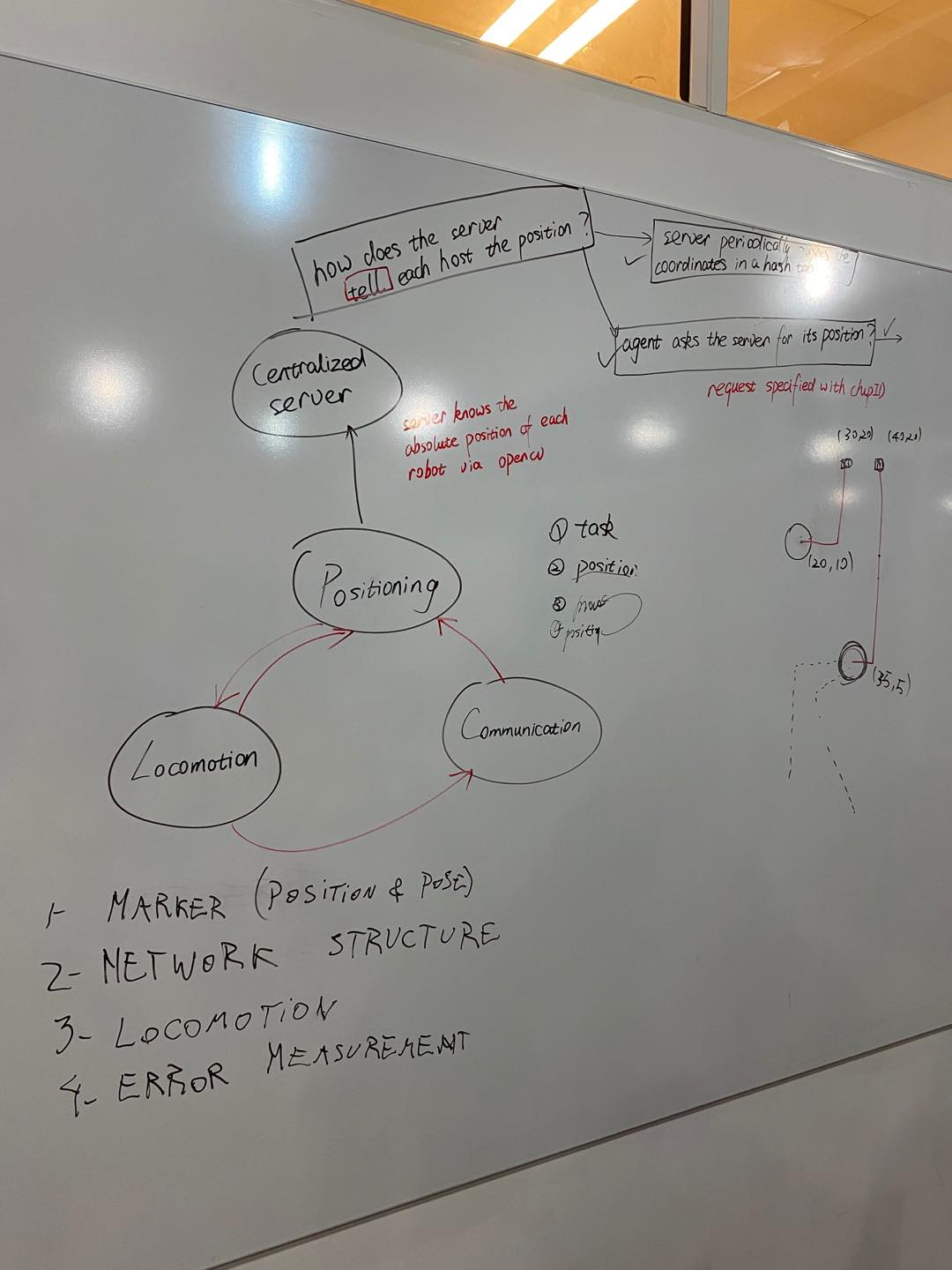
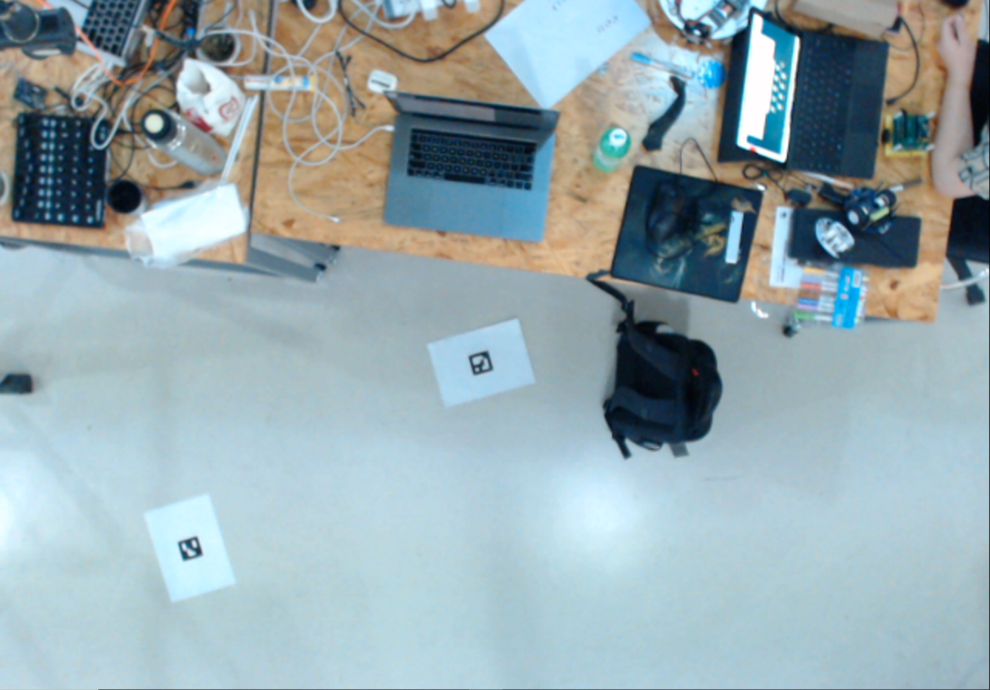
Though last year we spent a lot of time & effort on the distributed positioning system using IR, the petal shape IR radiation and the limited detection range were really bothersome. In this iteration, we decided to give up on the IR positioning and turn to having a camera hanging on the ceiling pointing down at the floor. To recognize the robot, each robot carries a unique arUco code on its back. A computer connected to the camera would use OpenCV to analyze the image and output the coordinates of all robots in the image. These coordinates would then be multicasted to an IP address using UDP. The UDP packets would be sent periodically, to guarantee the robots don't go off-course.
2. Communication:
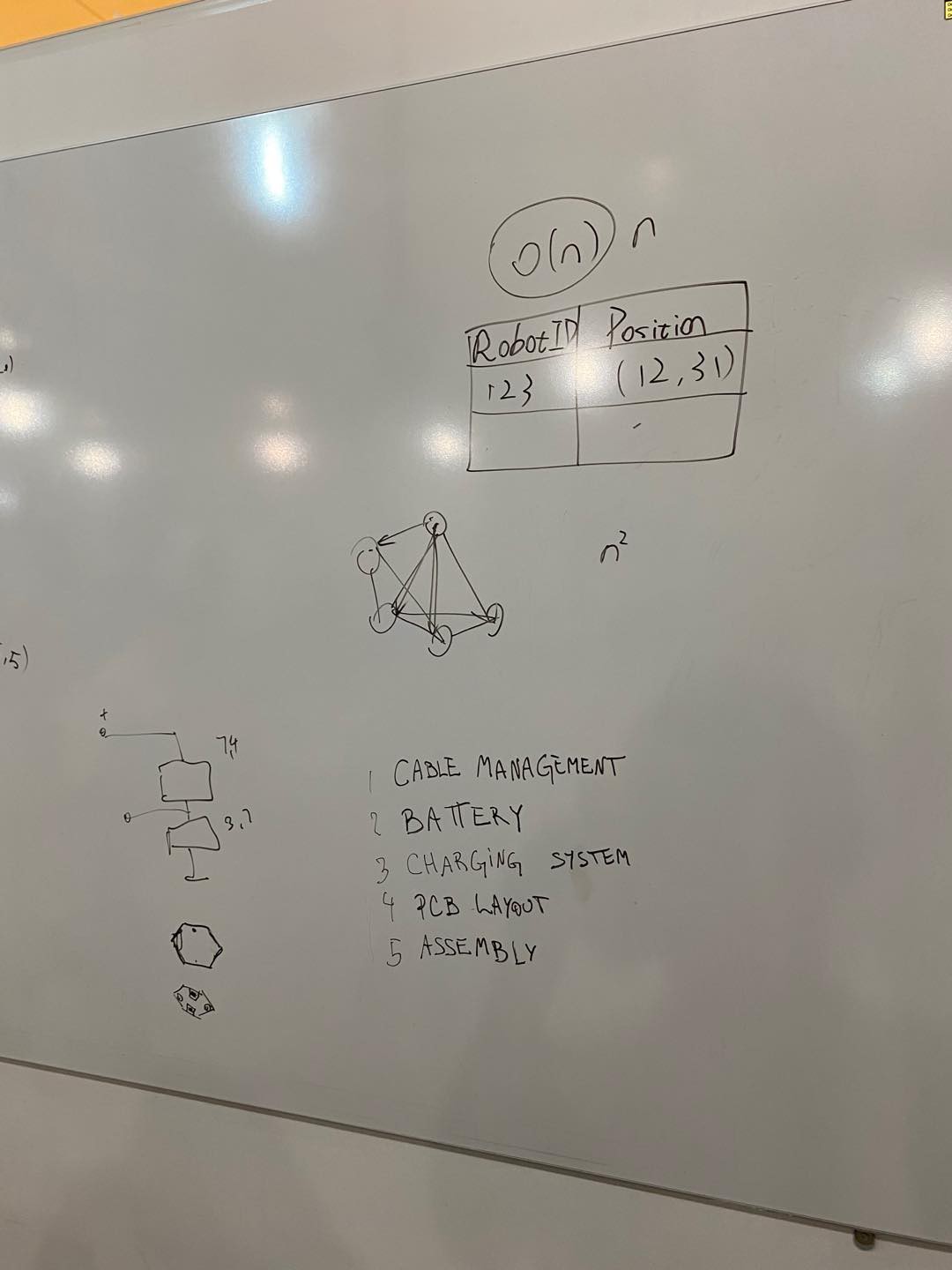
As mentioned above, we are using multicast for terminal-robot communication. The robots would be subscribed to a multicast IP that's dedicated for providing position information. We used mesh for robot-robot communication in the past, yet the tests we ran last year showed the communciation is always unstable and has a very limited range. There is also a chance that we get rid of mesh and turn fully to multicasting. But at this point we have not decided yet.
3. System structure
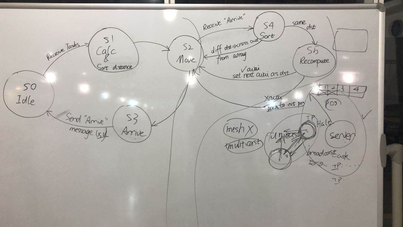
We are envisioning the system to carry out tasks like shape formation. The robots would receive tasks from the centralized server for coordinates to be taken up with. Based on Manhattan distance, the robots would distributedly calculate the nearest destination. They would move to the destination according to the Manhattan distance calculated.
Plans
The steps to develop the system are shown in the pictures below with order.
Finite State Machine of each robot
Week 1 Progress
Mechanical
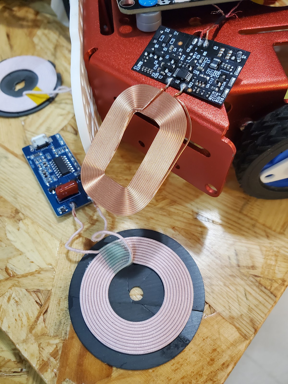
Wireless Charging:
We are experimenting with wireless charging modules and 3.7V rechargeable batteries, which is significantly easier than the wired charging with the 7.4V Li-Po battery packs on the previous design iteration. No more fiddling with cables. No wear and tear. However, some possible drawbacks include overheating and slower charging time.
Some tests with the wireless charging modules were conducted on the KittenBot (by soldering the receiver to the battery) to test the capabilities of the system. The results show a consistent pattern where the runtime is twice the charging time. However, the battery on the KittenBot is 2200mAh 3.7V, which is slightly different from the smaller 3.7V batteries (around 850mAh) that we intend to use. We predict that the smaller 14500 3.7 batteries will result in a runtime of around 4-5 hours.
Motors:
Since we changed the previous 7.4V Li-Po batteries to 3.7V Li-ion batteries, we also want to test out the 3V 105rpm gearmotors with encoders. As for improvements in cable management, we will be using the double-ended ZH1.5mm wire connectors, allowing us to easily plug and unplug motor cables from the PCB (if you recall, the wires were soldered onto the PCB in the previous version).
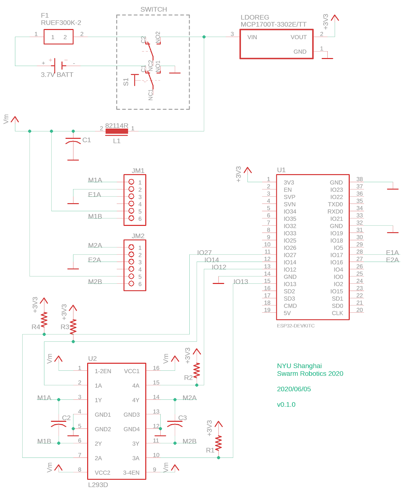
PCB:
We have designed a test PCB on Eagle (and sent it to a manufacturer) that can accommodate the new changes mentioned above. Another addition is an LDO Regulator (MCP1700) to regulate a 3.3V voltage for the ESP32. We are also trying out a new hexagonal shape for our robot. Let’s see if we like it. The plan is to examine the efficacy of the wireless charging system and examine whether the smaller 3.7V batteries can provide enough power to the motors and the ESP32.

Software
OpenCV
We first tried to learn open-cv to become more familiar with this new module, which is probably one of the most important and fundamental ones. After that, we proceeded with our project on the base of Zander’s code on camera calibration and arcuo code detection. We fixed bugs including how to invoke the right webcam connected to the computer and using the os module to better specify the file path, which ensures the code to be executed correctly on different machines. We also made some improvements on the aruco marker detection code. We used “adaptive thresholding” to reduce the influence from the shadow and natural light, which seems to be ruseful. We also used “perspective transformation” to make the camera better focus on the testing area, thus reducing the error of the world coordination (to around 5 cm?).
Multicast
We tested sending multicast from Python and receiving from ESP32. The terminal sending muIticast and the ESP32 receiving multicast are all connected to a LAN. The terminal emits multicast every three seconds. The tests showed very promising results. There is little delay in getting the message; the packages weren't corruputed during the tests as well, even when a large chunk of data (500 bytes) was sent.
Discussions
Become a Hackaday.io Member
Create an account to leave a comment. Already have an account? Log In.