 Bud Bennett
It was inevitable. Checking voltage accuracy is all well and good, but not enough. I have been thinking about how to provide a set of reference currents that are accurate enough to keep the 34461A honest for a few years. It's tough, but doable. The 34461A specs for DC current are:
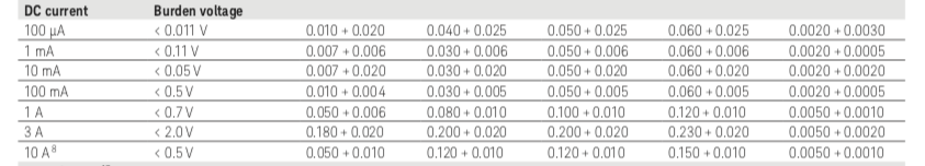
I tried to design for four reference currents, but gave up on the 100mA current -- too much power dissipation (1W) with the approach that I chose. So the current reference will provide only three currents: 10mA, 1mA and 100µA. In much of my work the accuracy of currents exceeding 10mA is usually not critical. The circuit below is what I came up with after a few revisions.
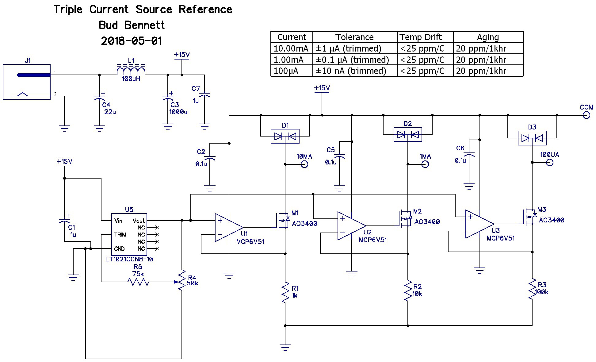
Current is just V/R. You need a good V and some good R's. This is a lot different that making an accurate voltage reference where ratios of resistors are important. In this case the absolute value of the voltage reference and the resistances determine the accuracy of the current. I chose the LT1021C-10 for the voltage reference. It has an initial accuracy of 10V±5mV. I added a trim to improve it, hoping to get 0.1mV trimmed accuracy.
I entertained the thought of just having the DMM measure the current through the resistor directly, but the burden voltage is too high and injects an unspecified error into the measurement. In the circuit above the DMM will connect between the COM pin and the current source to be measured — there is no need for large voltage swings. This makes the design a lot easier than a general purpose current source. Note that when the a current source is not being measured its current flows into a diode to limit the voltage swing to less than 1V below the supply rail, keeping the opamp and FET operating normally. When the DMM is measuring the current source the voltage across the diode will only be a few mV and the diode will have a negligible effect on the measurement.
The resistors, R1-R3, are expensive, 0.01% initial tolerance, 10ppm/°C tempco, through-hole types (~$7/each from Digikey). If the opamp has low offset and drift then the current in the drain of the FET transistors, M1-M3, should be very close to V/R. I chose the MCP6V51 chopper stabilized amplifiers for this reasoning: low Vos (15µV max), low Vos drift (36nV°C), very low input bias current (80pA), single supply operation to 45V, with moderate GBW, low supply current (470µA), in a small SOT23-5 package.
With a reference trimmed to 0.001% and resistors specified to 0.01% I expect the current sources to be on the order of 0.01%, if I don't screw up the PCB layout. This assumes that there is no significant leakage from gate-to-source or gate-to-drain from the AO3400 FET ( I checked -- the data sheet says < 100nA @ 12V VGS), so I'm hoping that there is less than 1nA of gate leakage current with room temperature conditions and lower gate-source voltage.
There are a lot of things to worry about with the PCB layout -- is the reference voltage compromised by load currents through traces?, or is the trace resistance low enough to not degrade the tolerance of the expensive resistors? Or are there parasitic leakage currents from nearby traces?
I added guard rings around the sensitive nodes -- the probe points used for the currents, and the high-voltage terminals of the R1-R3 resistors. Elsewhere I made sure that the PCB trace resistance was negligible where it made a difference (the GND terminations of R1-R3). The GND pin of the LT1021 connects to the GND trace of R1-R3 with little current flowing in the trace, so voltage error should be minimized. Also, the connections of the opamp and the source of the FET are Kelvin to the top pin of the resistor.
If the PCB parasitics are eliminated (or at least minimized) then all that’s left is the errors from the voltage sources (the Vref and opamps). The 80 pA input bias current of the opamp, and the value of the resistor. I expect the Vref to be trimmed to around ±0.1mV (±0.001%). The opamps contribute 15µV, or 1.5ppm, which is only 0.00015%. The resistors will dominate the error, so assume that the initial error will be very close to 0.01%. That’s about 5x better than the specification of the 34461A, but we haven’t accounted for temperature or aging errors.
Temperature drift of the reference is specified as <20ppm/C over its temperature range. The typical drift is quite a bit lower — 5ppm/C — and even lower over the small range of expected temperatures the circuit will be exposed to in the lab. The opamp is chopper stabilized with nearly zero offset voltage drift (36nV/C). That leaves the resistor with 10ppm/C. Over the ±8.5°C range of operation the current sources should move less than ±0.013%.
While the aging characteristics of the voltage reference are known within bounds, and the opamp errors are insignificant, the resistor aging is largely unknown. I saw references to ±0.01% drift after 2000hrs @70°C, or ±0.03% after 8000hrs at rated temperature and power dissipation, and a stability of X ppm after one year of shelf life. I guess we’ll see what happens. I don’t plan on running the current reference for months (or even hours) at a time to let it burn in.
I’m ready to order PCBs tomorrow.
Discussions
Become a Hackaday.io Member
Create an account to leave a comment. Already have an account? Log In.