Close
0%
0%

Upgrade Budget Laser Cutter

I have a laser cutter from China, similar to the K40 (50W 4060) it works out of the box but the software stack and UX needs work.

joeJoe
Similar projects worth following
I have a generic laser cutter from China. Similar but bigger than the most common K40 laser cutter. I decided to spend a little more to get most of the upgrades that most people seem to do when they buy the K40, unfortunately, it still comes with the M2Nanno Controller board and chinese software and pirated (?) corelDraw. I didn't bother to install the software and instead installed and used the excellent open source replacement K40Whisperer https://www.scorchworks.com/K40whisperer/k40whisperer.htmlI still wasn't happy so now i plan to replace the controller with a GRBL compatible board. This is my Journey.....

Laser cutter specs out of the box:

  • 50W laser (generic)
  • 400 x 600mm cutting Area
  • Air Assist (aquarium pump which seems to work well)
  • Water cooled (aquarium water pump, also working well)
  • Water flow sensor (to shutdown laser if water is not flowing)
  • moving Z platform with DC motor (manual up and down control)
  • Honeycomb bed
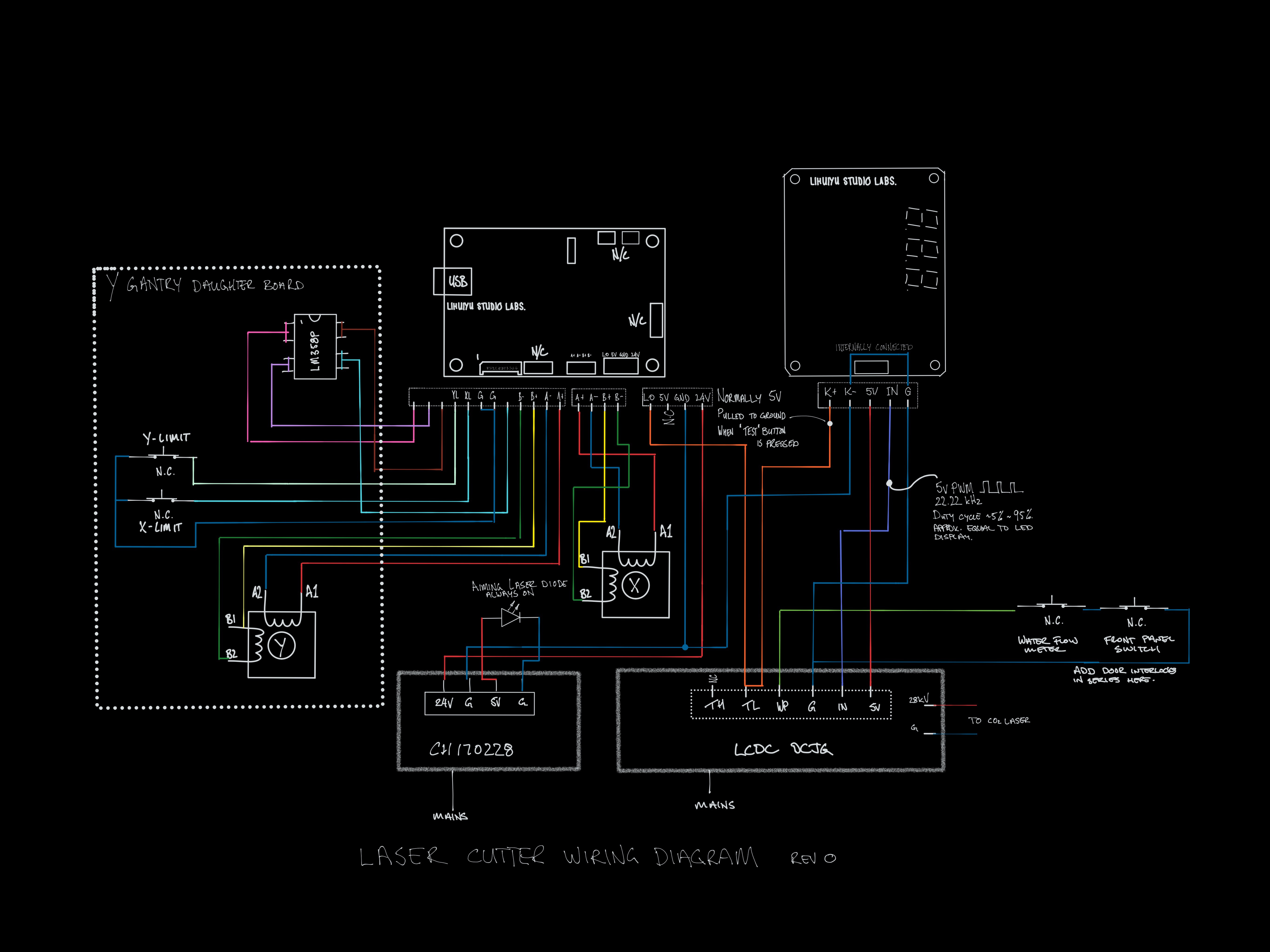
  • Lihuiyu studio lab M2Nano controller
  • Lihuiyu studio lab 6C6879-LEDPAD-A laser power controller
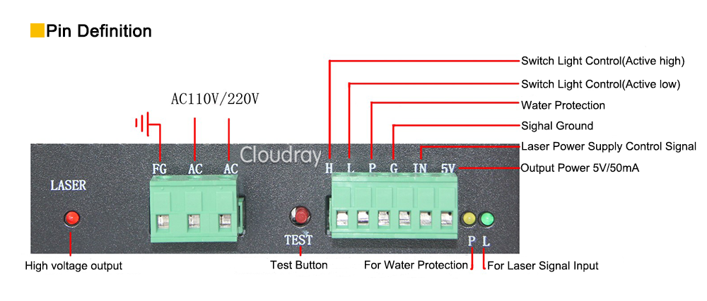
  • LCDC DCJG-50W Laser power supply unit
  • CH170228 power supply. 240vAC in --> 5v & 24v DC out
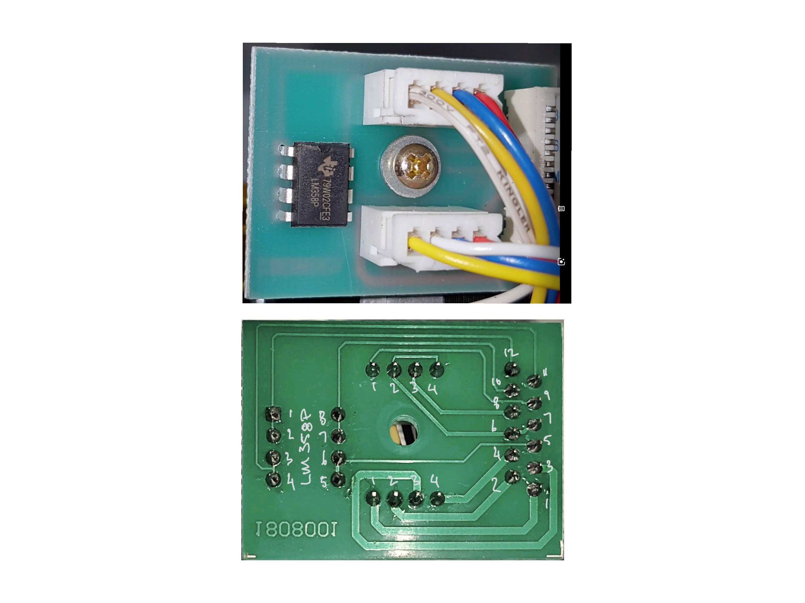
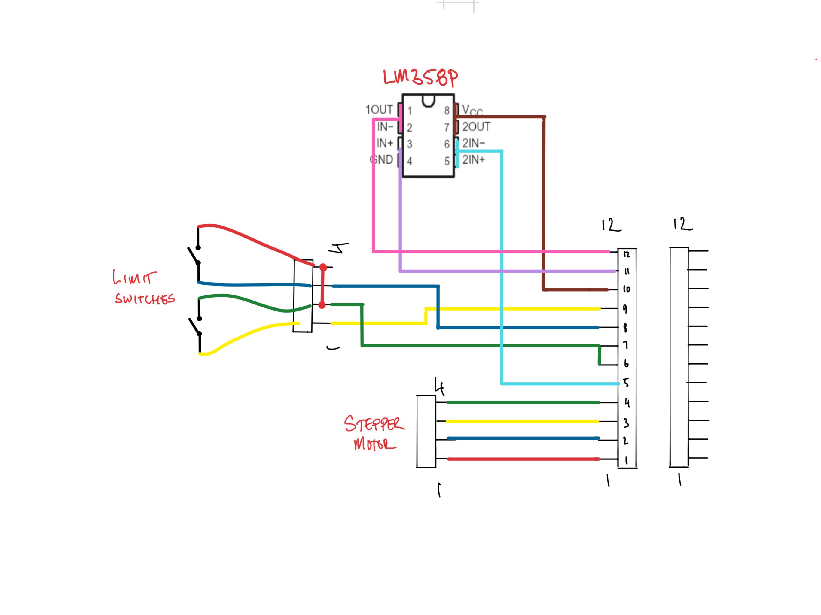
  • limit switch board with LM358p op-amp. (debounce?)

And now for the wish list

  • User friendly software tool chain 
  • full g-code control of the laser power. (this is currently set manually at the start of each operation)
  • untethered operation - ok to connect to upload the job but not leave a pc there for the duration.
  • Limit the maximum current supplied to the laser to prevent burnout
  • Safety
    • add door interlocks to stop the laser firing when a door is open
    • led on the front panel to be lit whenever the laser is firing
  • Cooling system
    • keep the water flow interlock on the cooling system
    • monitor and display water temperature
    • shut down the laser if the water temperature goes above a certain limit
    • provide audible / visual alarm for over temperature
  • Manually control the laser to focus, mirror alignment etc using "Test" button (software control would be ok.)
  • Gcode control of the Z axis (low priority)
  • Hardware jog controls (Next Project)

Original wiring diagram.pdf

Wiring diagram ‘out of the box’

Adobe Portable Document Format - 843.43 kB - 04/28/2019 at 12:02

Preview
Download

  • The Wiring Diagram

    Joe04/28/2019 at 11:45 0 comments

    I have gone through the wiring and sketched it out. I also took out the laser power control board (the one with 888 on it) and pit it in a logic analyser. The IN pin sends a 22.22kHz PWM with a duty cycle that more or less matches what is shown on the display. The K- pin is pulled up to 5v normally and to ground when the test button is pressed. 

  • Stepper & limit switch daughter board

    Joe04/26/2019 at 11:20 0 comments

    This daughter board is mounted on the y gantry and provides a connection point for the Y-axis stepper motor and the X & Y-axis limit switches

    It connects to the main board with an FFC ribbon cable. After taking a look at Don’s Laser Cutter Things I found out that is is a 12pin 1.25mm pitch FFC cable and ordered a connector from RS Components. I searched for “CONN FFC VERT 12POS 1.25MM”.

    After looking at the circuit, I am really confused. I have sketched out the circuit below to make it a bit clearer. If anyone knows what the opp amp is doing, let me know. I will take a look at the controller later to see if I can work out what is happening....

  • Laser PSU

    Joe04/25/2019 at 12:26 0 comments

    Like everything on this laser, it is very difficult to get any documentation for the PSU.

    Based on the markings it is a LCDC DCJG-50W. The photo below shows the low voltage connector. I will leave the high voltage connector to the laser allone. 

    Out of the box, it is setup as shown in the photo below. The laser intensity is controlled by the IN pin. The power controller on the front panel provides a signal 0 to 5v (or PWM?)  and the laser power is adjusted accordingly. 

    I think that the TL pin is connected to the "test" button and the laser is on when it is pulled to ground. 

    I plan to connect the spindle / laser PWM from controller to the TH (high on). I think that i should still be able to use the TL pin for testing but i am not sure what the power level will be if the IN is not connected. Maybe I should have a voltage divider pot next to the test button so that I can set the power with that. I'm Not sure how that will affect the power during normal operation though. I might need to do some testing. 

    I also spoke to the supplier of my laser cutter about max power that I can run the laser tube at. He said 25mA so hopefully i can find a way on the PSU to limit the current accordingly

    Finally, I have been reading all over the internet about installing a ammeter in series with the laser tube to make sure that I am not exceeding the rating so i think that i will do that to. I am a bit worried that it may affect the operation of the laser. i have seen that some of the lasers have the ammeter fitted in the factory so maybe is to not a problem.  let me know in the comments if you have any experience.

    I'm also not sure if there should be some sort of "laser enable" pin that i need to connect to the controller. 

    PSU LV connection
    LCDC DCGJ- 50W PSU LV connection


  • The new controller board

    Joe04/25/2019 at 11:48 0 comments

    I have been looking around for a replacement board for the motion and laser control. There are lots of boards to choose from, including some that can be swapped out directly but i like the look of the board by Bart from buildlog.nethttp://www.buildlog.net/blog/2018/11/grbl_esp32-development-board-version-3-1/

    The manufacturer of the laser cutter has made some interesting choices for the motor and limit switch connectors (12 pin FFC) so I have decided to make my own board based on the schematic at the link above with some modifications for my case.

    When I was researching parts, I realised that everything was available as pre-made modules which will save me a lot of time and hassle soldering smd parts. It will also let me assemble to circuit on a breadboard and get it working very quickly.

View all 4 project logs

Enjoy this project?

Share

Discussions

Mike Szczys wrote 05/06/2019 at 19:51 point

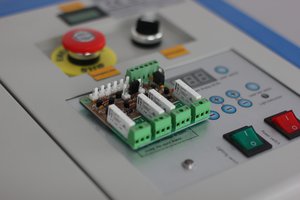
Great wishlist... especially the interlocks. Looking forward to watching as this comes together!

  Are you sure? yes | no

Joe wrote 05/07/2019 at 11:55 point

Hi, thanks for the encouragement. Now I just need to find the time.

  Are you sure? yes | no

Similar Projects

Does this project spark your interest?

Become a member to follow this project and never miss any updates