 Xabi Z
We want to replace the ancient simplicity of the Siemens manufactured board by the modern complexity of the Raspberry Pi Zero W. The project, however, also aims to keep the component count low and avoid using unnecessary components if they are not compulsory: The phone already has its own speaker and microphone? So why replace them with their modern counterparts? Yes, I know an old carbon microphone may not sound precisely crystal clear, but it will add another bit of vintage touch to our project (and a 1980 flavored frustration to the one talking to us on the other side of the line); our smartphone already has all required communication functionalities and chatting applications? So why re-implement them on the Pi? Let's just figure out how to connect our new old rotary-phone to our old new smartphone. The solution will be squeezing the Bluetooth capabilities of the Raspberry Pi Zero to the maximum.
Wiring the rotary dial
Another important point to preserve the touch of this old phone is conserving and using the rotary dial as it was intended to. Old rotary dials require the finger to be inserted in the hole corresponding to the number to be dialed and turning the wheel clockwise until the stop. When the wheel is released, a spring rewinds it back to its original position. On its way back the dial opens and closes a contact several times producing a train of equally spaced pulses. The amount of times this contact is closed and opened corresponds to the dialed number. The diagram below shows such a pulse train:
/Year_5/ELC-523-Advanced%20Communication%20Systems/Telephone_Instruments/Images/Pulse_Train.GIF)
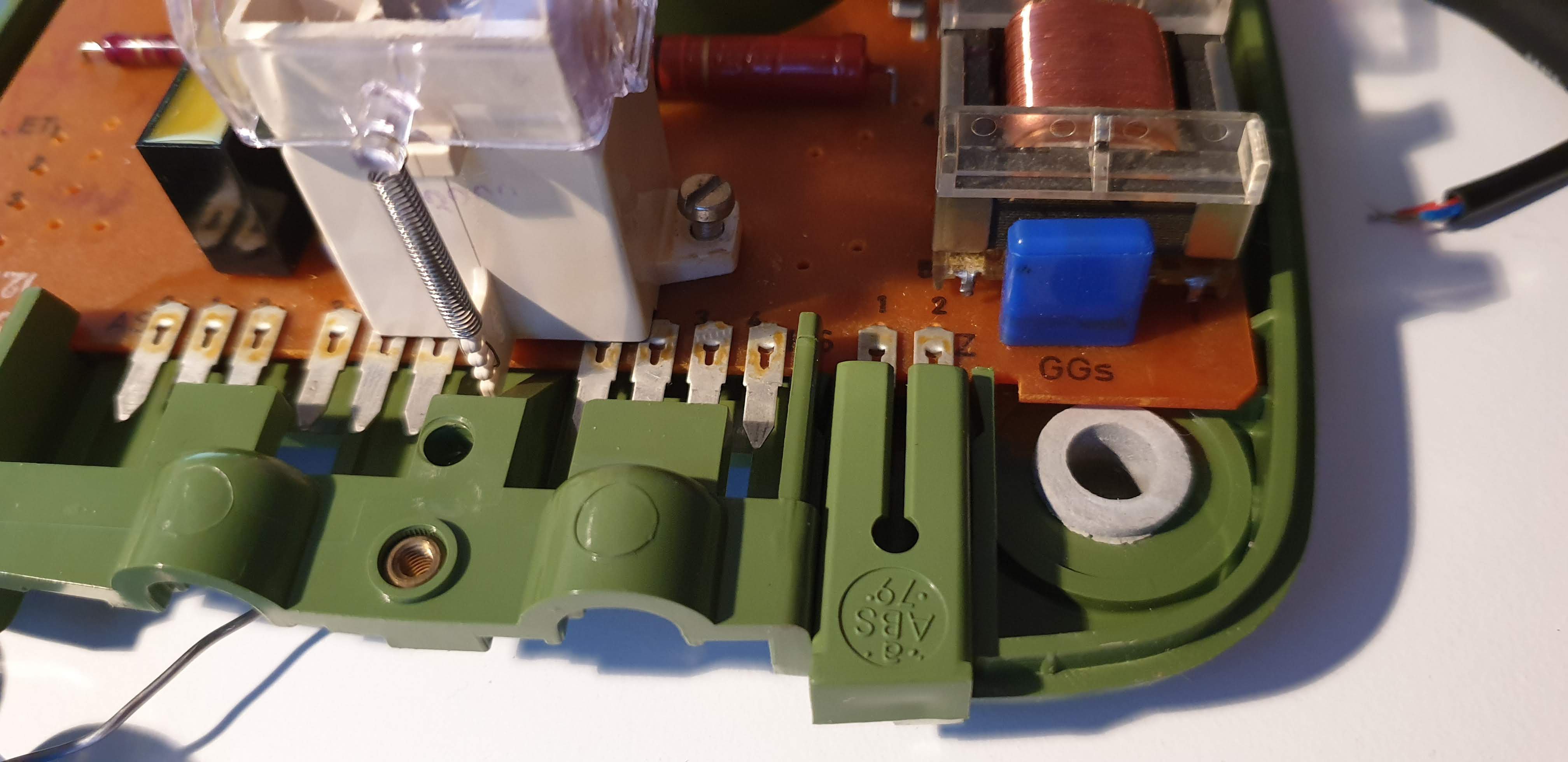
A four pin socket named NS (Nummerschalter) links the circuit board to the rotary dial part.

First of all, all unnecessary components have been soldered out of the circuit board to free up space for the placement of the Pi and the sound-card as well as the OTG cable linking both and additional cabling to redirect the microphone and speaker. However, the old circuit boards is a perfect support for all the pins and our devices, thus it has not been completely removed.
After checking the circuit diagram and careful cross-checking with a multimeter, the circuit between the NS pins 1 and 2 seems to close when a dial-pulse is produced. These pulses can easily be read using any input-enabled GPIO from the Pi.
Wiring the hook
The hook switch operates in the opposite way to the intuitive one. The circuit is closed as long as the receiver is hooked up and it's opened when the receiver is picked up. The circuit is opened and closed between the pins 2 and 4 of the NS header.
Because the rotary dial impulses and the hook switch share the pin 2, a voltage (or ground connection) can be fed to this pin and the value of pins 1 and 4 read using the GPIOs of the Raspberry.
Wiring the receiver
The receiver encapsulates the carbon microphone and the speaker. The covers of them can be removed exposing both parts attached through a rubber ring which was already merged with the plastic with the pass of the years, Although the audio quality produced by both parts will not sound so great there is no real need to replace them and re-attach modern microphones and speakers as replacement.
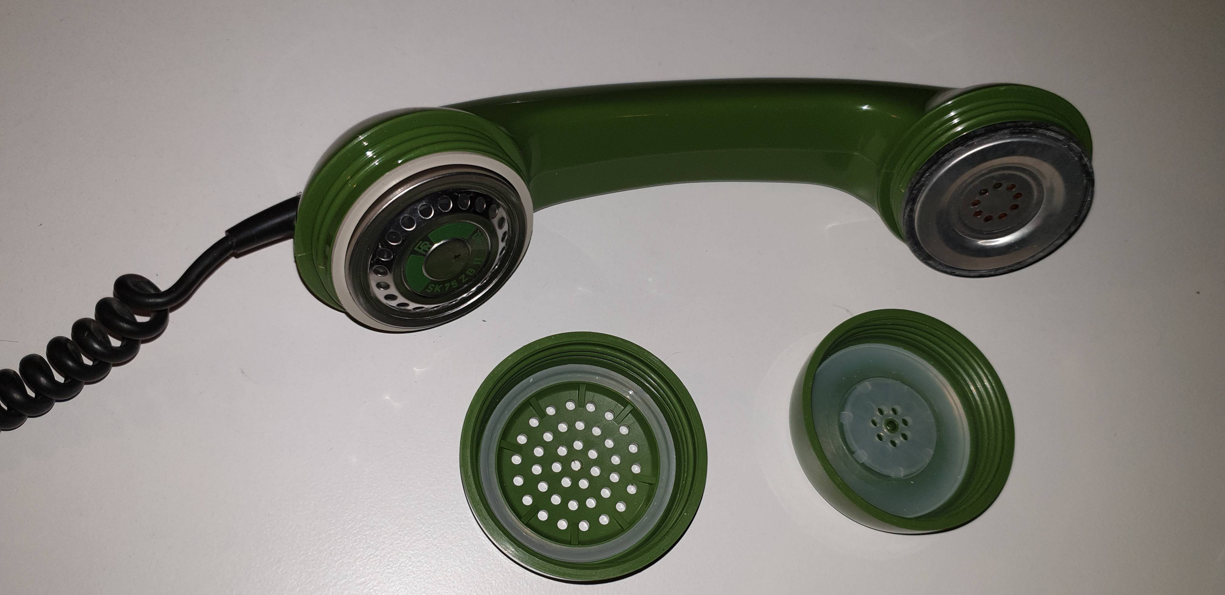
In order not to damage the rubber rings, the wires correspond to the microphone and the ones from the speaker were found by trial and error using the sound-card. In this very model the pins 1 and 2 from the header labeled 'HS' correspond to the microphone and the pins 3 and 4 to the speaker.
Another important fact to notice is that due to the fact that the speaker and the microphone signals are mixed for transmission, there is a short circuit between their pins. Because of that, the track from the other side of the circuit board starting from speaker and microphone pins was cut to isolate them.
[insert pic of cut track]
Since we cut this tracks, from this very moment the phone is nonoperational for the traditional use. The phone's net connection cable plugged to the socket branded AS can therefore be removed and discarded. There is a sealed additional socked on the very right of the connectors labelled with 'Z' which shares the pins of the speaker probably intended to connect some sort of hands-free loudspeaker. By removing its green plastic placeholder we have an ideal hole from which we can pull out our USB power cable.
The only thing missing is to connect the sound-card, the dial and hook signals, and the power to the Pi. The final wired device looks like this:
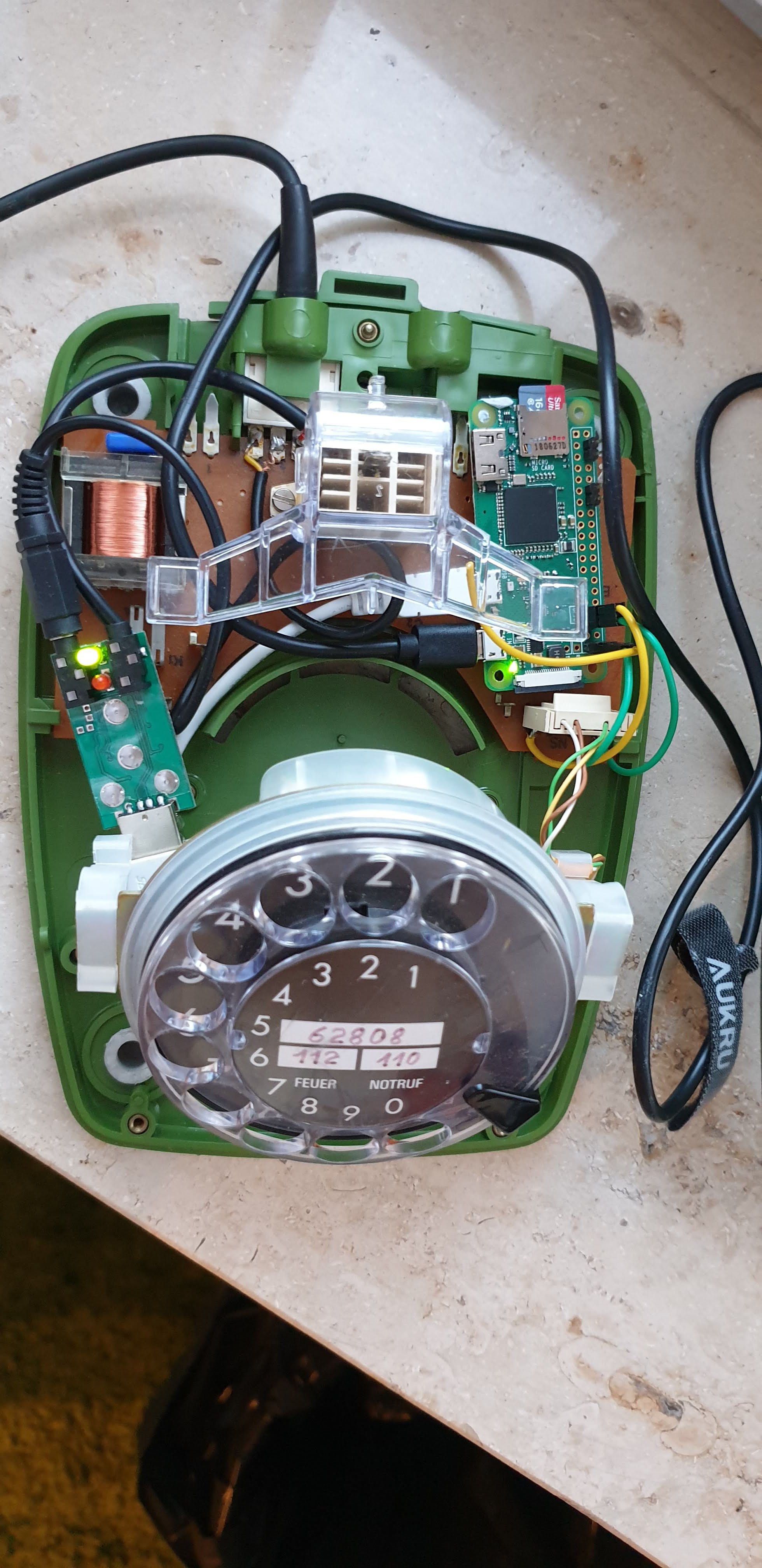
Once the wiring is completed we can cover the phone and head to the computer for the software side of the project.
Discussions
Become a Hackaday.io Member
Create an account to leave a comment. Already have an account? Log In.