 Paul Gould
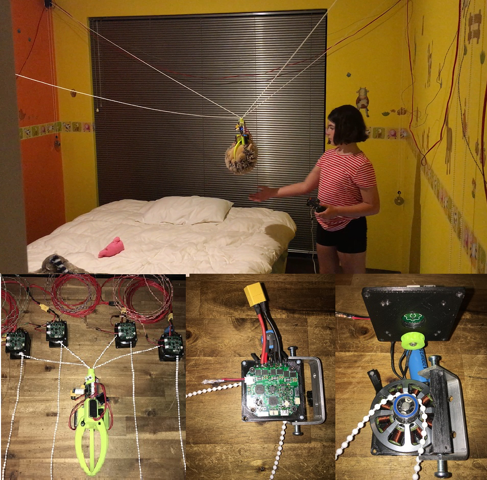
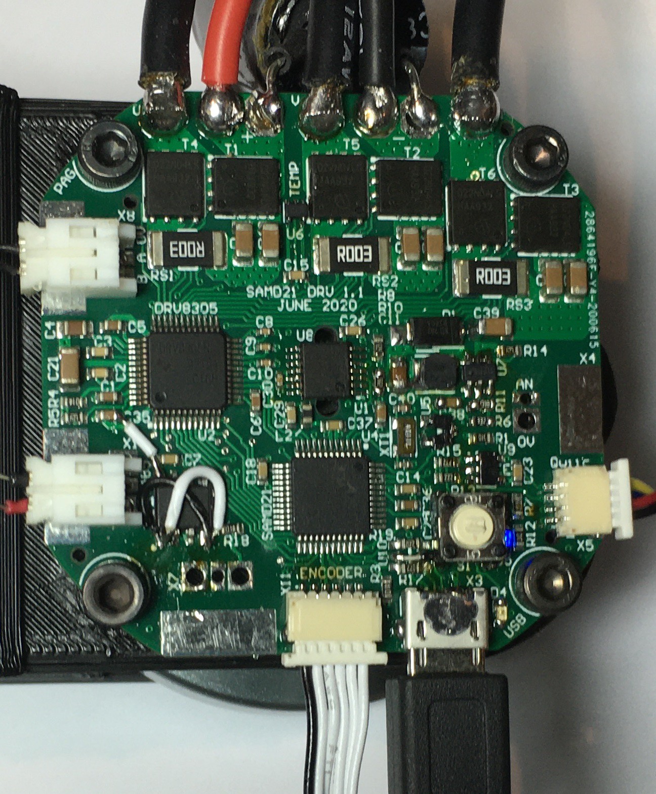
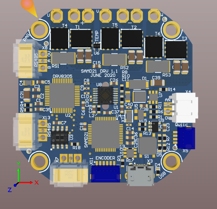
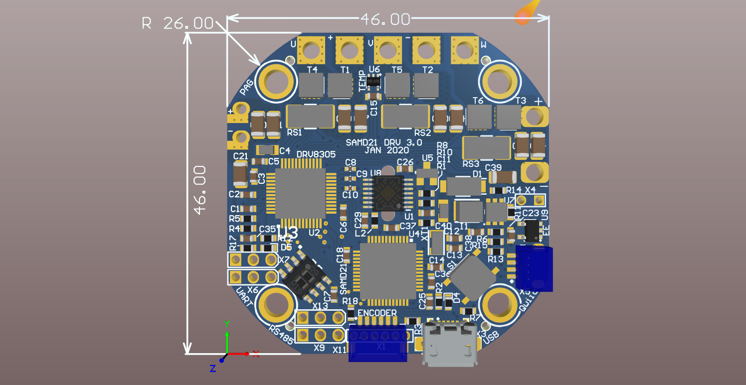
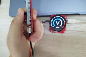
Ardunio M0/Zero/SAMD21 running Actuator Operating System paired with Brushless FET Driver, MOSFETs, Absolute Magnetic Encoder, EEPROM, dual voltage regulators, temperature, USB and RS485. 30V @ 30A ~$US50
Uses
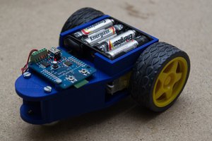
- Brushless Motor Robotic Joints (with SEA)
- Brushless Motor CNC axis controllers (closed loop)
- Electric Skateboards motors
50mm square and 58mm round
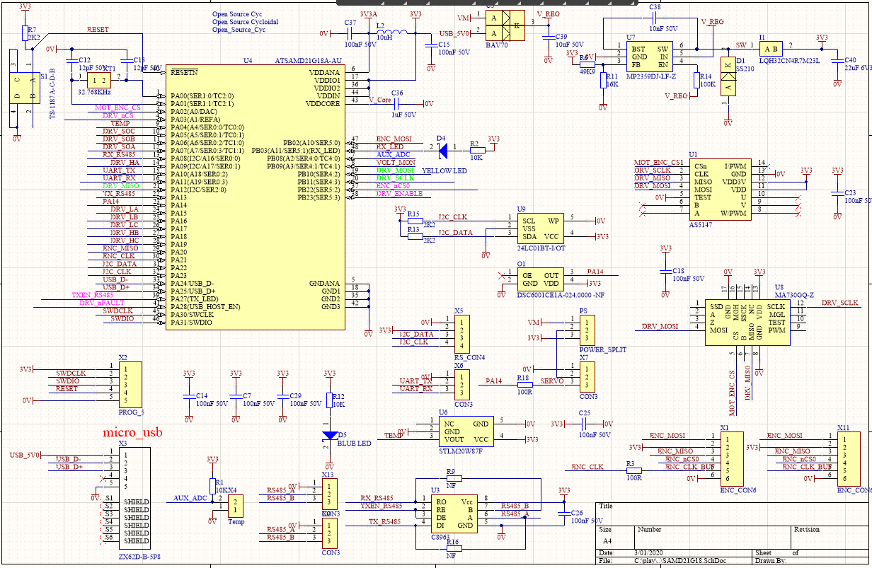
Ardunio Actuator Operating System
- Standard Ardunio Boot code (Reset x2 to enable)
- Foreground 10kHz motor control task update rate
- Sinusoidal or Field Oriented Controller (FOC)
- SPI with DMA operation for on board Absolute Magnetic Encoder (motor position)
- DMA is slower, may just use registers
- Optional Hall effect (motor position)
- SPI with DMA operation for external Absolute Magnetic Encoder (1 or 2 daisy chain)
- 3/6 phase centre aligned PWM motor control (registers/no libraries)
- 6/7x ADC free running Sequential operation with DMA(no delay)
- 3 Phase Motor Current Measurement
- Mosfet Temperature
- Battery Voltage
- Motor Temp
- potentiometer joint position
- PID joint controller
- low level interrupt foreground tasks
- RS485/USB/UART communications
- RS485 UART with IRQ packet receive and transmit
- optional Step/Direction
- RS485/USB/UART communications
- Background Tasks
- OLED I2C (standard Arduino Libraries)
- Mosfet Driver configuration
- EEPROM (standard Arduino Libraries)
- User Functions
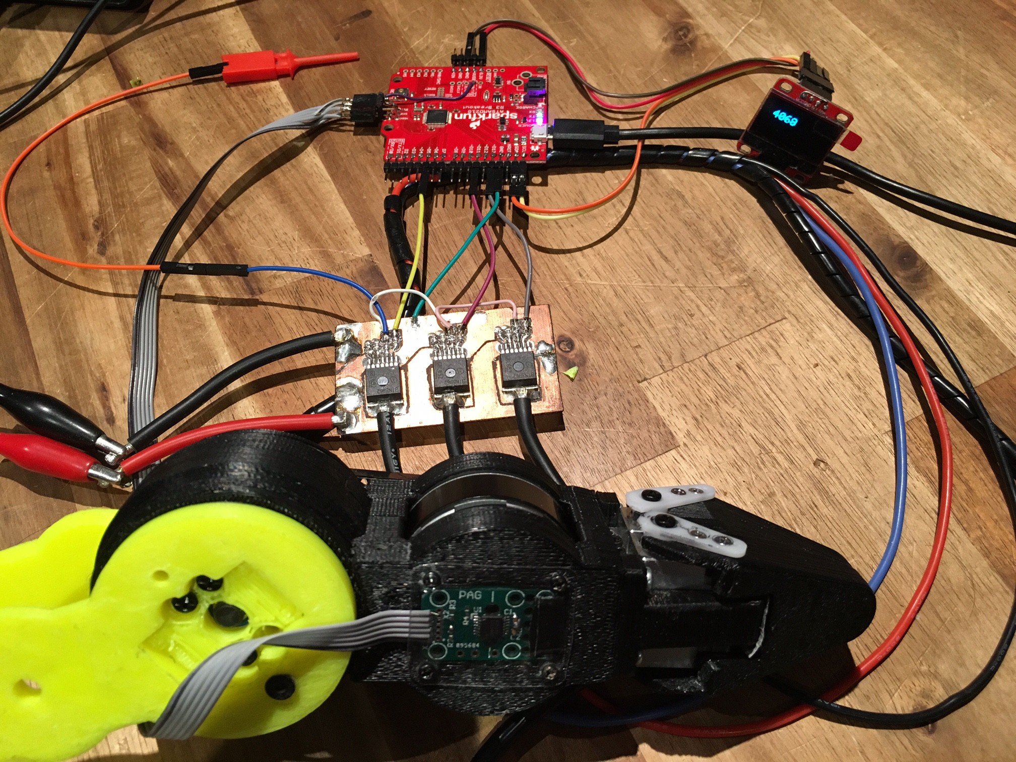
2- 8 Cell LiPo (6-34V)
Center positioned Absolute Magnetic Encoder AS5047/AS5147/AS5048 or MA730/MA702 with Alignment holes
3V3 Switching regulator from either LiPo or USB (Diode switch over)
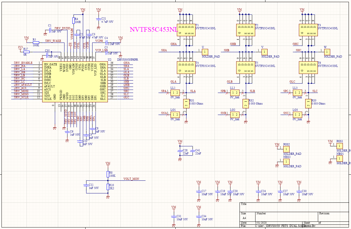
6x 2mOhms 40V N-channel MOSFETS (BSC022N04LSATMA1) Power SO-8mm
3x 3mOhms Sense Resistors
3 Current Shunt Amplifiers in DRV8305N
MOSFET Temperature sensor
External connections for
- USB programming, configuration and control
- Connectors for RS485 for daisy chain operation
- Header for UART
- Connector for external Temp Sensor
- Qwiic I2C (OLED display)
- Connector for External Absolute Magnetic Encoders (SPI) in Single or daisy chain configuration or Hall effect sensors or potentiometer
- Only one spare Digital IO for Servo, Fan or Limit Switch
Population Options
- External 24MHz Oscillator (maybe removed in next revision)
- Extra Power supply Caps
- Remove RS485 and use as second TTL UART (maybe removed in next revision)
- MOSFET Heatsink and fan


 Makerfabs
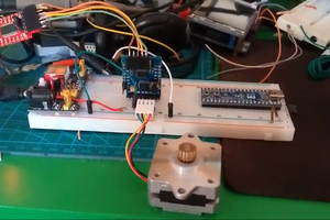
 Tom Van den Bon
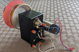
 JP Gleyzes
This project is completely wrong or the person who made it did not give all the information. Scheme and code are completely incompatible. Circuit Operation does not seem possible. Don't waste time and money in vain.