To continue my last post, I'll share the progress I've made on getting the camera closer to doing what it's supposed to. What follows is a technical description of how the system that I've been building works.
Grayscale image to single-bit pixels
The block matching FPGAs receives 8-bit grayscale images from each of the two remap FPGAs over a simple 8-bit parallel bus. This is a total of 8 images, 4 per remap FPGA since they each have 4 cameras. These grayscale images are downsampled by 2x in each dimension from the color image resolution. They are cropped vertically so they are only 90 degrees tall rather than the full 180 that's captured in color. Since they are 135 degrees wide, and the full-res image is 360 degrees and 3840 pixels wide, that means the dimensions are (135/360) * 3840 / 2 = 720x480 pixels.
Recap of 3D image stitching/block matching/optical flow
We slice these grayscale images into 3 vertical sections: left, center, and right. Each of these thirds is a 45-degree slice of the full 360-degree horizontal image. Because we have 8 cameras that are distributed equally, that means our cameras are angled at 360/8 = 45 degrees from one another. From this, we know that if we have cameras A, B, and C arranged like so:
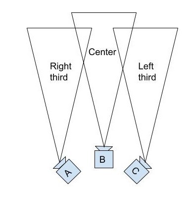
Then the right third of camera A, the center of camera B, and the left third of camera C must all be pointed in the same direction. If they're all looking at something that's an infinite distance away, all three of those slices should be the exact same image. However, we want to show depth in our output images. Therefore, we'll use the left third from camera C and the right third from camera A for the images that we feed to the right and left eyes of the viewer when they're facing in that direction, respectively. As the viewer turns their head to the left, their right eye will go from seeing the left third of camera C to the left third of camera B. Since these cameras are in different locations, that can result in a strange-looking transition between the two images, as nearby objects will be shifted to the right in images from camera B compared to images from camera C. To blend the images, we want to calculate the offset between the positions of objects in the left third of C and the center of B, and then we can shift those objects in the output image to blend the two images together as our final output image transitions between cameras.
I'm doing this optical flow calculation using block matching, where you select the a block of pixels from one camera and search for a matching block of pixels in the image from another camera. Ideally, the block with the least differences will be the same object as the original block.
Back to the main topic: block matching optical flow
To run block matching as fast as possible, I'm converting the grayscale images to images with one bit per pixel. This is done by creating a filtered version of the grayscale image, where each pixel is the average of a 16x16 block of pixels around it, and then comparing each pixel in the grayscale image to the local average at that point. If it's above it, the bit pixel is 1 and otherwise it's 0. This should preserve edges and details while simplifying the image as much as possible. Then, to do block matching we just do an XOR of the original block to the candidate block and count the bits, otherwise known as calculating the hamming distance.
This works for areas of the image with the right amount of detail, but completely fails on areas with no texture or repeated patterns (walls, floors, etc). We want to save the block matching results that are correct and discard the ones that are just random noise. How do we do that? My method assigns a confidence score to each block match. Right now, this confidence is just the minimum (best) hamming distance minus the average hamming distance for all the blocks that we tried to match to. This actually works surprisingly well to predict how good a block match is. See the results below:
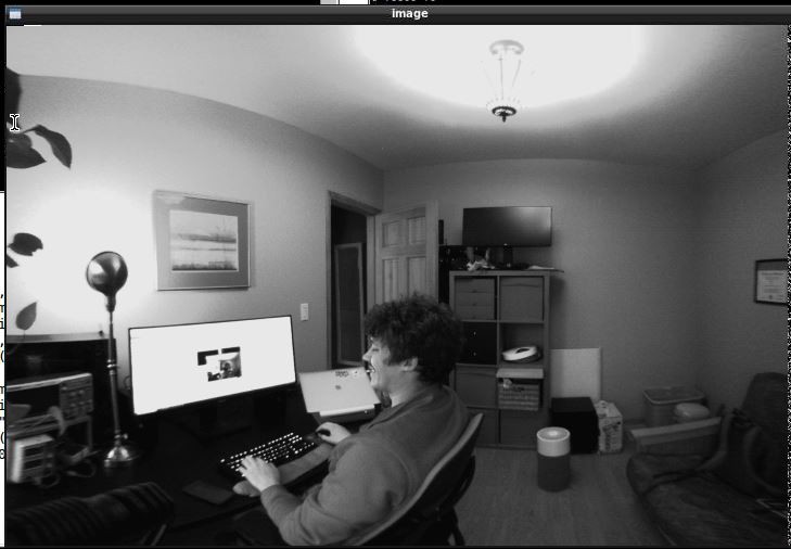
Above: The full 135-degree wide grayscale image from the center camera. We receive this from the remap FPGA

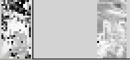
Above: The center third (45 degrees) from this converted to 1-bit pixels
Above: The depth and confidence. This one requires some squinting to interpret.
On the left is our depth output, with darker pixels being closer. The black pixels at the top are completely wrong - those are the ceiling which doesn't have enough texture to figure out the depth. The gray blob in the lowerish center is me, and I'm darker than the surrounding pixels since I'm closer to the camera than the background is. On the right is the confidence. As you can see, the wall and ceiling are darker than the detailed areas. This means our confidence is lower, which it should be, since the depth estimates there are totally wrong.
What's next?
What I'm working on now is how to process the depth and confidence, preserving depth in high-confidence areas and propagating that to lower-confidence areas. Once that's working, we need to upsample and stream the depth back to the remap FPGAs so they can use it to stitch the color images!
Discussions
Become a Hackaday.io Member
Create an account to leave a comment. Already have an account? Log In.