 Octavio.Makes
Edit: Fixed the thingiverse page with the STLs!
This is the written project page for my video on the same topic:
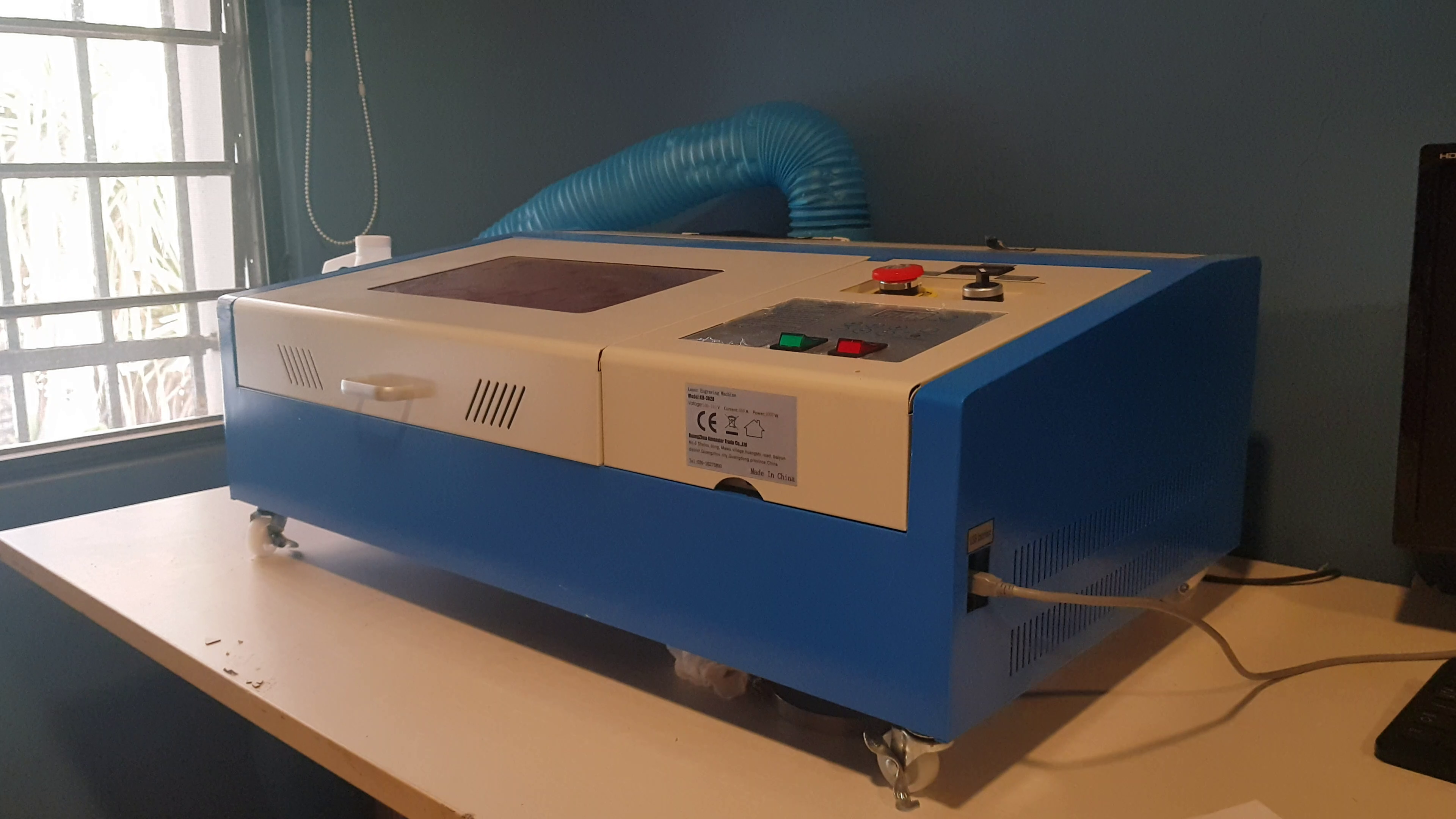
This is the K40 laser cutter. The epitome of cheap Chinese manufacturing. Cheap enough to risk it, and just expensive enough to warrant some confidence. It is go-to laser cutter/engraver for makers on a budget, not only for its price but also for the community behind it. Which is very important, considering that its up to you to finish the manufacturing and to protect yourself from accidental fires due to poor wiring.
The manufactures made quite a few compromises to make a machine this cheap. While some design choices were rather smart, many were, to put it lightly, hasty or desperate. So, it’s very common to see upgrades online that tries to fix these poor choices.
This video is the start of a series of videos where we will make incremental upgrades to this laser cutter until we have fixed most, if not all, of the common ‘issues’ it came with.
Among many of the issues common with this machine, I find the extraction system to be very frustrating. It’s probably because they threw a bathroom extractor on the box to be used as a smoke extractor. And since this machine is not exactly a bathroom then is not surprising it severely underperforms. So, I decided to start with here because of that and also because I already had all the parts I needed laying around.
Let’s start by pointing out the issues of this extraction system first:
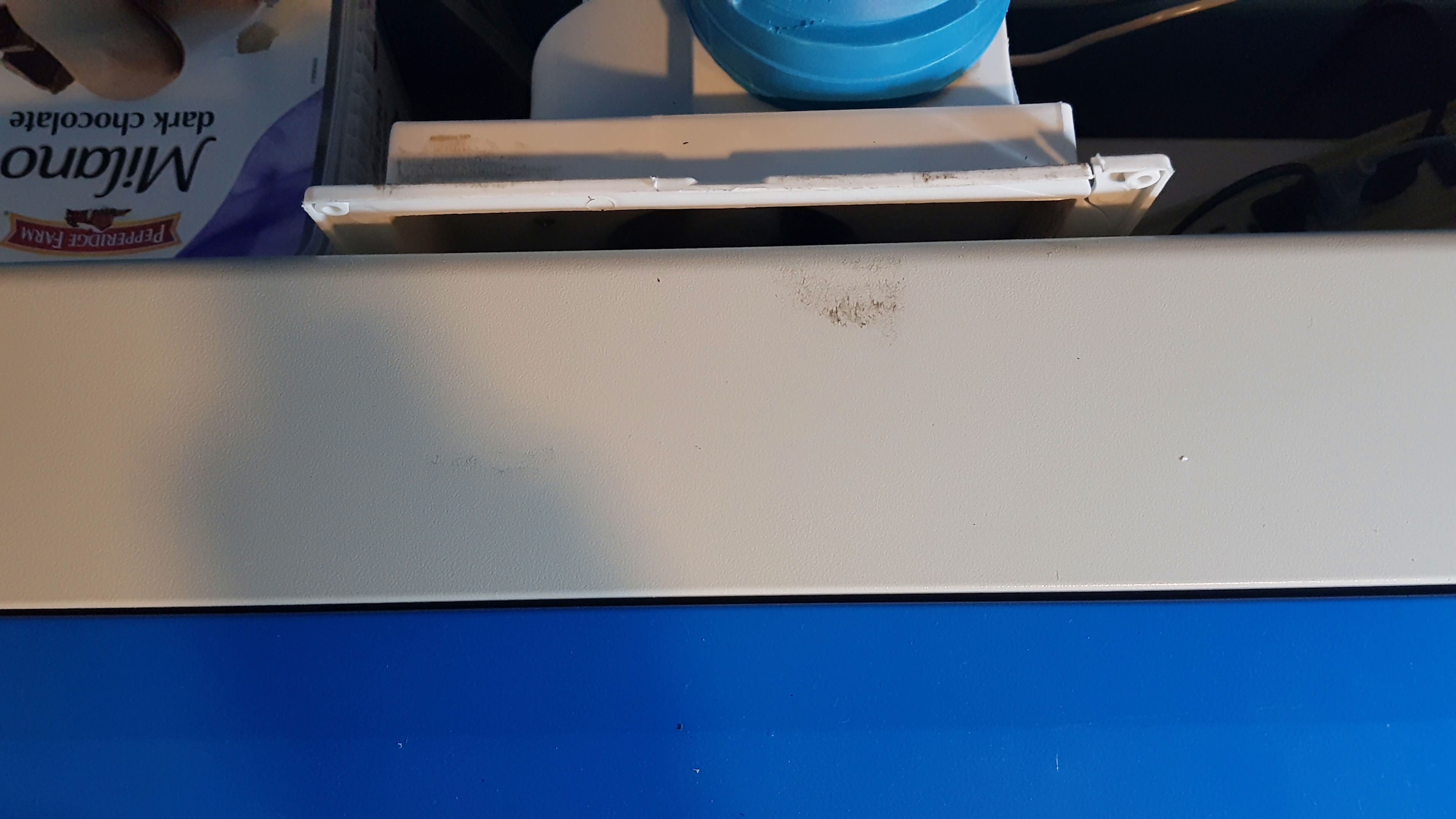
- The extractor’s fit is too loose: the manufacturers employed a slit-in system that allows us to quickly install and remove the extractor when needed. This, however, cause the fit to be excessively loose. The extractor sucks some air from the sides reducing overall airflow across the bed and allows some smoke to leak into the room.
- The extractor is too big: the base plate is unnecessarily big. This blocks access to the tube chamber and require us to unmount every time we want to look at the tube.
- The extractor is not powerful enough: this causes the airflow to become slow at the front end of the machine.
There are a ton of ways we can solve all of these issues and, if that is all we care about, then any solution that fixes the problem is a good solution. But we know that some solutions are better than others. In order to constrain the problem further let’s consider some design aspect that our exhaust system should have in addition of the fixes from before:
- Quick mounting and dismounting: the exhaust should be easily installed and removed without compromising the air-tightness
- Adjustable speed: this will allow us to regulate the speed to reduce noise production.
Let’s start by selecting a fan.
The best way to move air through the flexible duct is an inline blower. This is mainly because flexible ducts create a significant pressure drop that needs to be overcome and inline blowers sustain a bigger static pressure than regular fans. That means that for the same airflow, regular axial fans need more power and generates more noise than an inline blower. For short segments of flex duct, the drop in pressure is rather small and not a deal breaker.
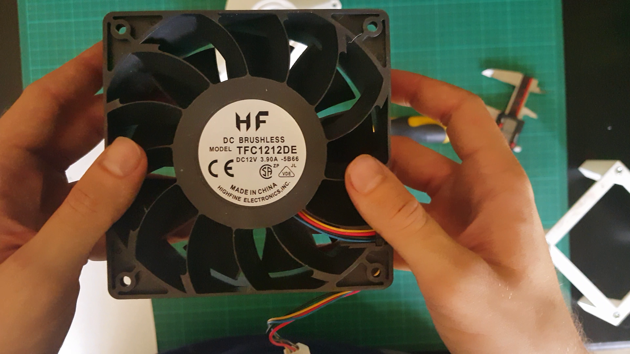
While all of that is true, I went with a 120mm computer fan that the seller claims to be very powerful. According to the seller, this is a 12V 3.9A Axial Fan, capable of up to 252 CFM or 7.16m3/min (airflow at no load),1.41 in h2o or 35.88mm h2o of static pressure, runs at 4800 rpm with tachometer and pwm control and generates 65dBA of noise. It sells for about $20 which is good for this specs. I tested the current draw with my incredibly unscientific power supply, and it registered about 2.71A, which is way out of spec. Don’t be surprise if all of these specs are off. I’m still using this fan mostly because I already had it from university project that I sadly didn’t document it enough, only this picture:
It is often recommended that you should install the fan or blower at the end of the flex duct where the smoke exhaust. There are multiple advantages for this approach, maintaining a negative pressure on the duct is a preferable practice when exhausting gases, also the noise will be further apart from the operator and some claim that fans are better at pulling air than pushing air (citation needed). But it’s a huge inconvenience because powering the fan that’s far away from the machine requires you to install longer cables and that can get messy fast.
Even with all of these advantages, I chose to place the fan right at the exhaust hole of the machine mainly because of compactness and because is easily reachable.
So far, we’ve been ignoring the optimal design in favor of an easier compact design. This doesn’t mean that our design so far is worst, it only means that this design is somewhat inefficient in some ways. And that’s a compromise I’m willing to live with, making it a better design even if it’s an inefficient design.
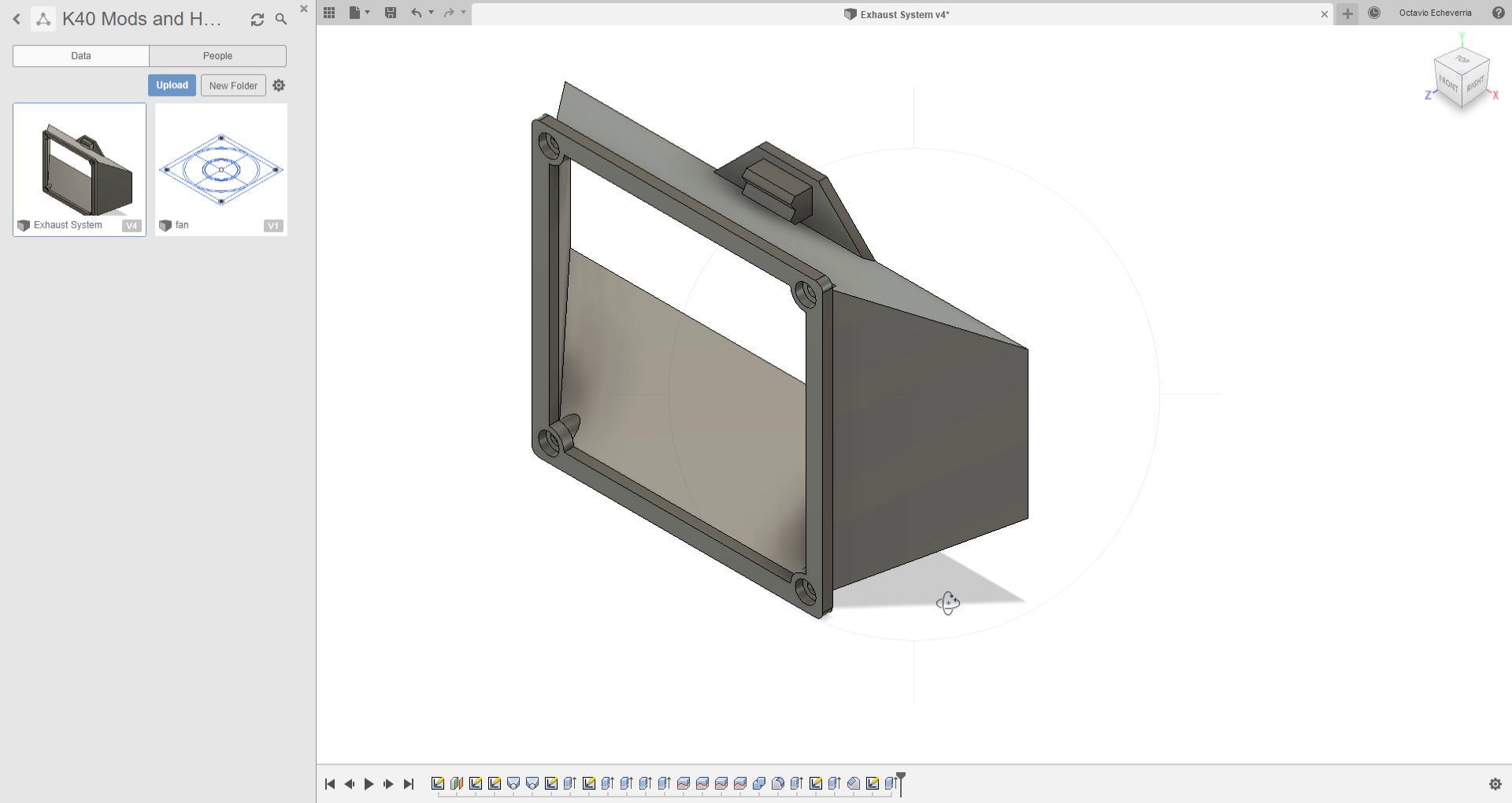
After taking some measurements and making some drawings of what we want, we can start making a 3D model of all parts that need printing.
The first part we are designing is the shroud or diffuser that adapts the 120mm fan intake to the rectangular outlet in the machine. My first approach was using some bungee chord to clamp the diffuser over the hole.
I started by drawing some profiles in fusion 360 and using a loft command to make the transitions between both geometries and that worked very well. I made some holes for the screws that will clamp the whole assembly together and some tab for the bungie to rest in.
I exported the stl and printed the part using the following parameters that I figured had just enough strength for this application. After a few hours of printing, I removed all support material and made a quick examination of the print to conclude that everything went as expected. The fit between the fan and the shroud was good and it fitted with the machine the way I intended.
Using some foamcore, I made a quick outline of the silhouette of the end of the shroud the met the machine to be cut and used as a support piece. This restricts the movement of the shroud and served a double purpose in aiding the quick installation and removal of the assembly.
Using some bungee, I proceeded to install the part. Just to realize that there is no way for this bungee to provide enough force to clamp the shroud in place. I had to redesign.
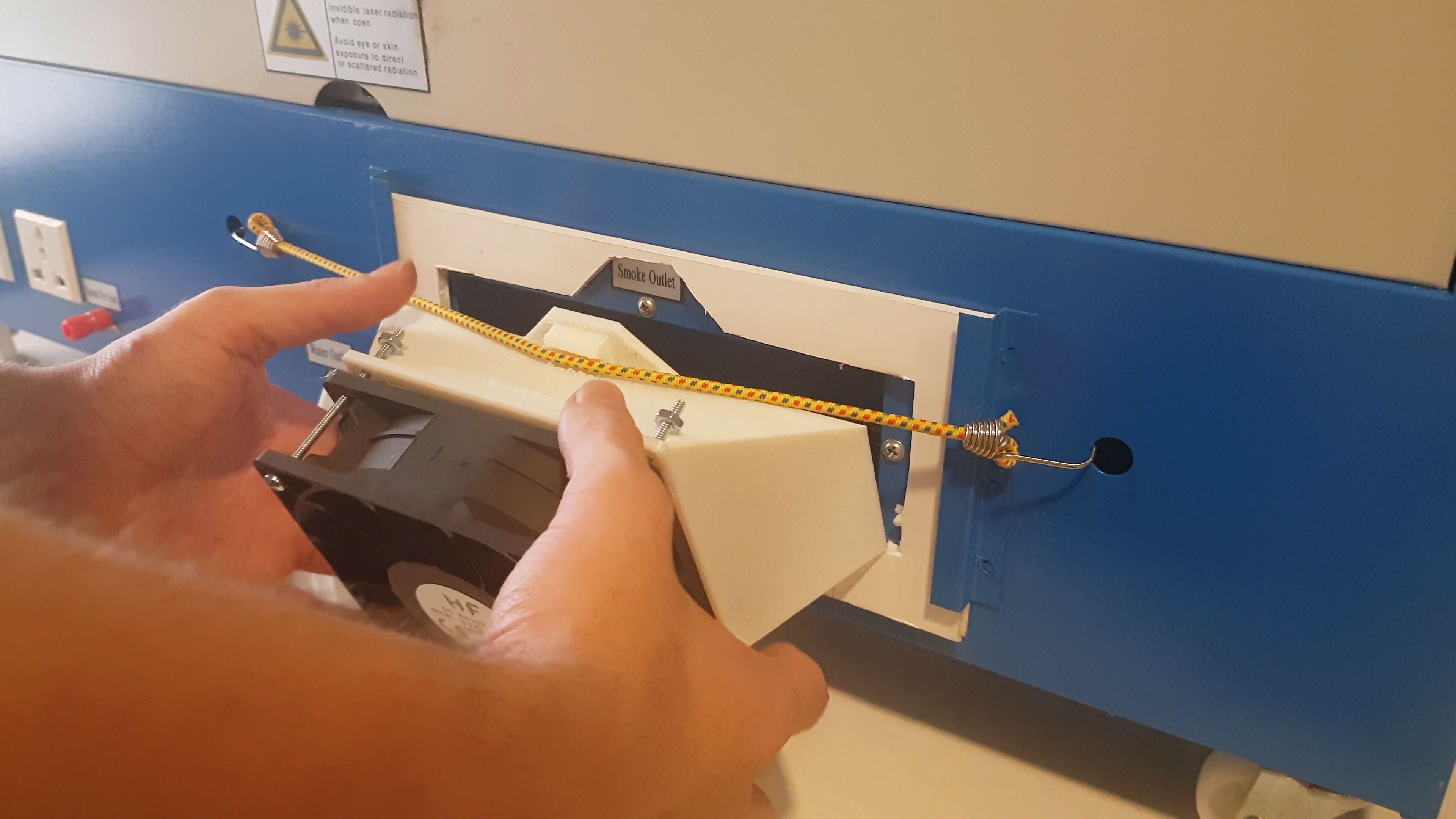
My next approach was to make the shroud fit inside the outlet of the machine and using some tabs to prevent the assembly from falling over.
I modified the design to use 4 smaller tabs instead of 2 big ones to hold itself and made the shroud smaller to make it fit inside the rectangular hole. Printed, cleaned and mounted the fan to it. Sadly, the mating piece of the shroud was a tad bigger than I expected, so I had to iterate again.
After the appropriate modifications to the sketch, the whole design adjusted itself automatically, this is the biggest advantage of timeline-based 3D modelling. This time the piece fitted nicely to the machine. It hold the weight of the fan with no problem and was easily installed and removed. You can find the 3D model here.
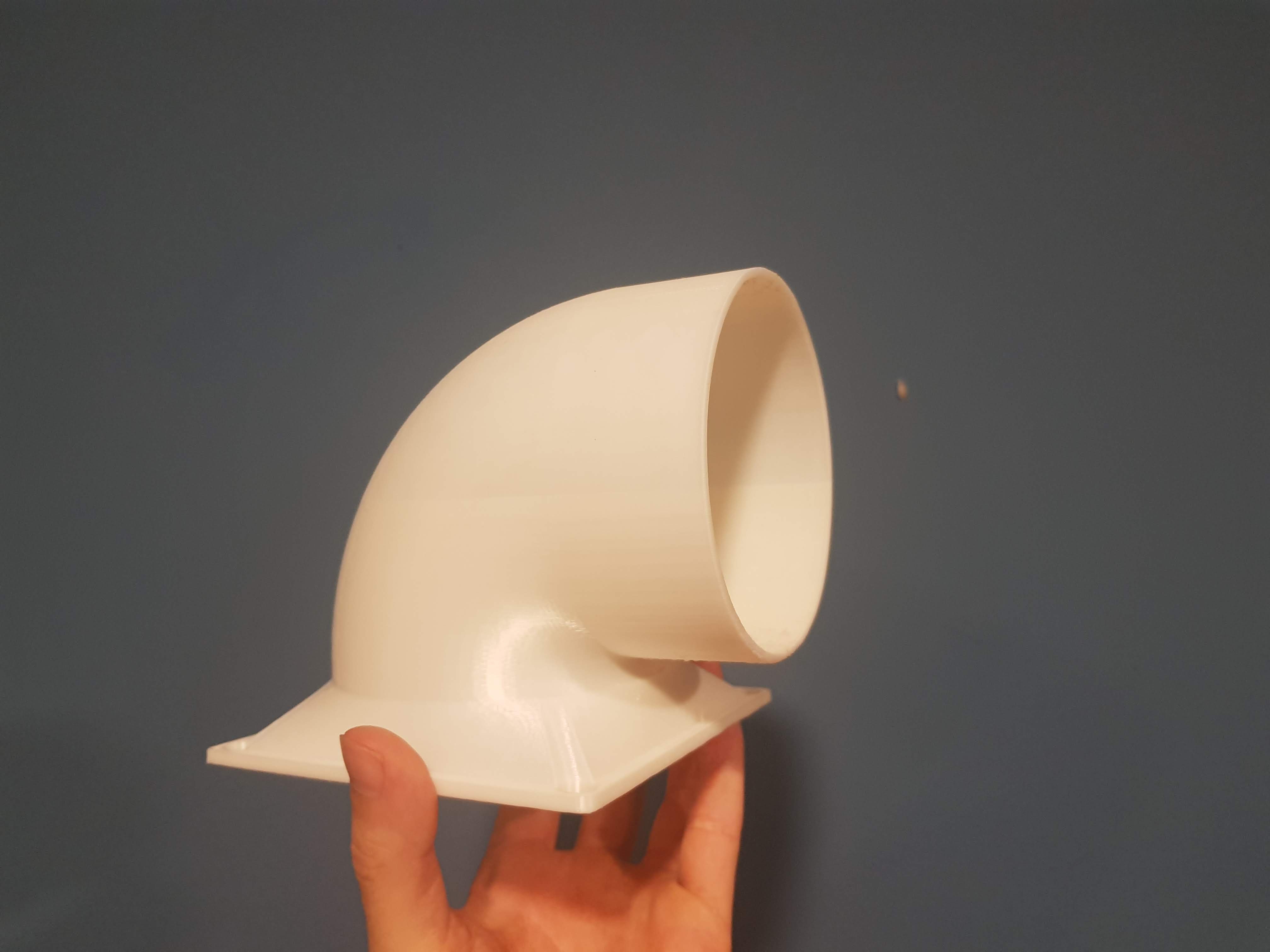
Now we need to design the part that connects the flex duct to the fan. This part is more complex because we need to make a shroud that will adapt both geometries while it also makes the smoke take a 90 degree turn and exit to a side the machine. This is to make it compact and easier to install and uninstall.
Again, I made a loft from square hole to a circular hole then connected that part with a sweep of a circle that went around a quarter turn. This is the model I ended up with. Its significantly bigger than the other shroud and way harder to print because of the amount of support material needed.
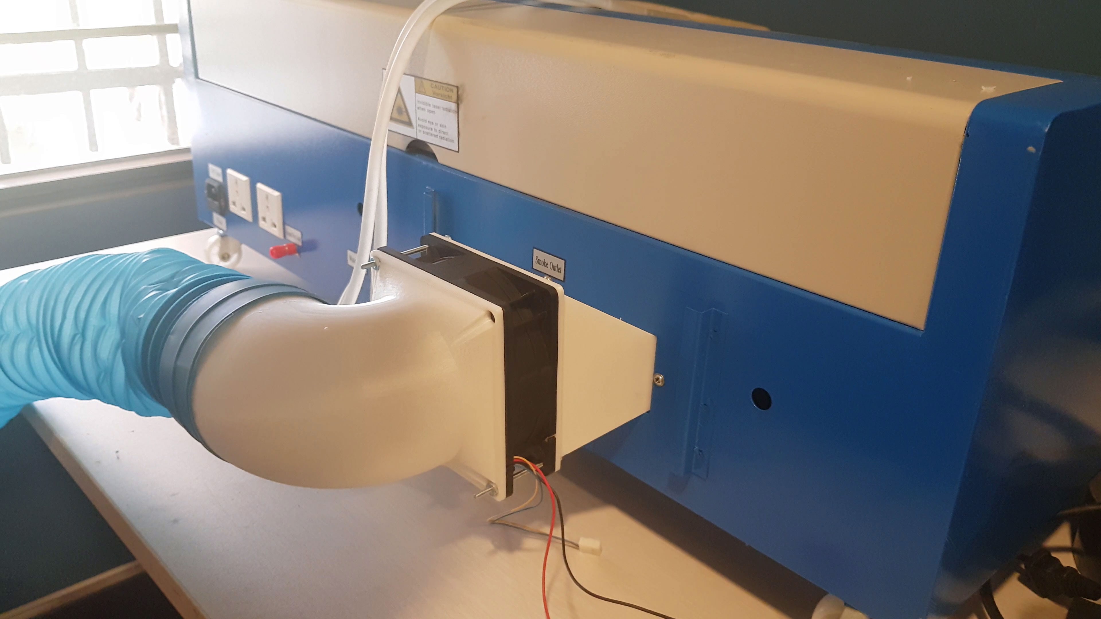
I exported and printed the model which lasted 7 hours using the same settings as before. The print turned out ok and thankfully the support material were easy to remove. The part fitted nicely with the assembly and it mated correctly with the flex duct. Again, you can find the model here.
I installed the whole assembly on the machine and it hold itself well. Immediately after powering up the noise was indeed loud, as expected, but also muffled by the duct. This made it noticeably quieter than running the fan alone.
I made some very unscientific experiments comparing both extractors. And unsurprisingly, this 3D printed extractor outperformed the bathroom extractor the machine came with but not by a lot.
Looking back at our goals we set for this mod, we’ve already made some good progress. We are only missing one goal and that’s speed adjustability. Luckily for us, this fan comes with PWM control.
To test this control signal, I set up a breadboard with an Arduino nano and potentiometer connected to analog A0. The potentiometer position gets read by the Arduino, gets mapped to the pwm range of the Arduino and it outputs a pwm signal to the fan. I also added a pull-down resistor to the pwm pin in the fan to avoid starting at full speed when the Arduino is booting. This is the code I used:
#define FAN_PWM 3

int sweepval;
int pwm_val;

void setup() {
Serial.begin(9600);
Serial.println("Starting up...");
pinMode(FAN_PWM, OUTPUT);
}

void loop() {
sweepval = analogRead(A0);
pwm_val = sweepval/4;
Serial.print(sweepval);
Serial.print(" ");
Serial.println(pwm_val);
analogWrite(FAN_PWM, pwm_val);
delay(10);

}
Experimenting with set up I noticed that the fan shutsdown when the PWM signal is low enough. The fan will take a while before turning on again once the signal is present. It seems that the fan needs to operate at a minimum speed to avoid a shutdown. Perhaps we can fool the tachometer in software? I haven’t found a good solution for this.
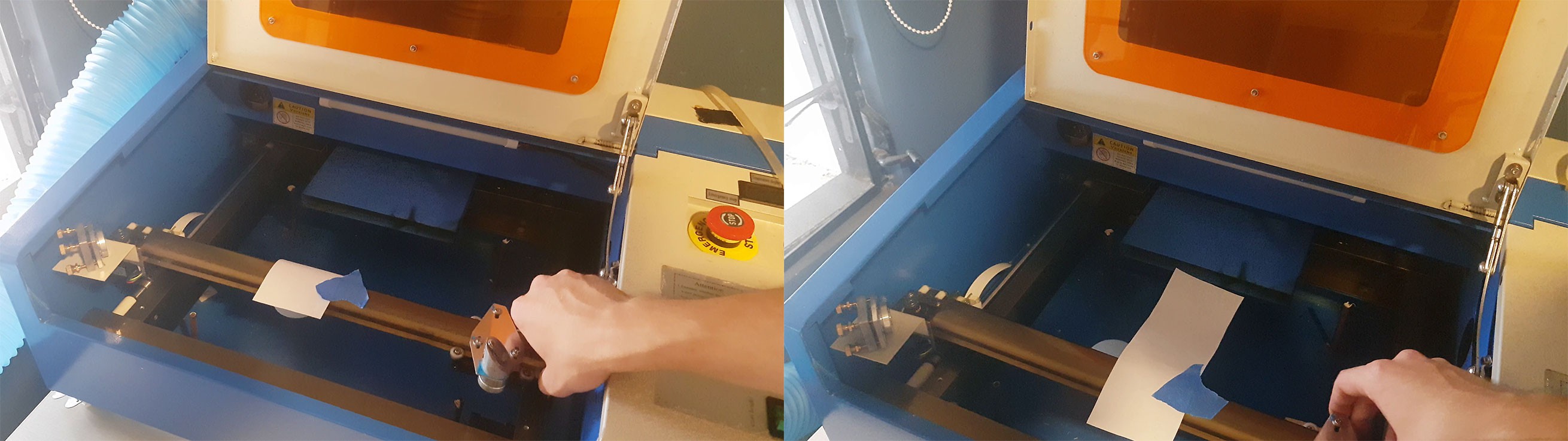
Moving on, I proceeded to install the fan and the experimental circuit to the machine and powered it up using my sketchy power supply. The fan seemed to run just fine and it regulated its speed just like on the bench. From previous experience, I remember that rastering images generated a ton of smoke, so I loaded a file I’ve used before to k40 whisperer. I placed a piece of cardstock on the “bed” and set the power to 20% (this percentage might not mean nothing at all) and the speed to 200 mm/s and began the raster.
This machine is not terribly fast unlike others, but hey, you get what you pay for! The whole operation lasted about 11min give or take. After it was done, I examined the results. Since we don’t have a reference to compare it to, it was clear that a test with the old extraction system was necessary. So I set up the machine with the old extractor and raster the same image with the same speeds.
After a few minutes the machine was finished. Comparing both results it was clear that the changes were not that significant in this case. Both extractors caused charring in the cardstock at the same place and it seemed like the old extractor caused less.
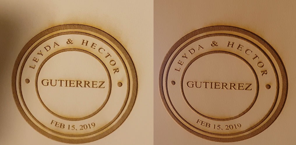
Although its hard to see, the smoke generated with the old extractor was thicker than the smoke generated with the new system. This is probably because the old extractor pulled less air in and it allowed the smoke to thicken up before it was extracted.
Different materials and with different operations will yield different results. And cardstock is the only material I had right now. Time will tell if this new extractor is any better than the old bathroom extractor and when I finally gather enough data to show, I will surely share it in a follow up video. Maybe in a version 2.
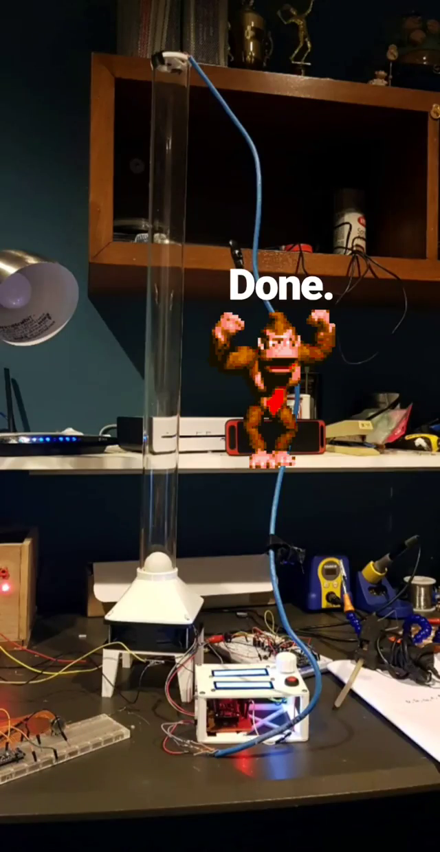
To wrap this project up. I made a small board with some Veroboard. It contained everything that was on the breadboard plus a voltage regulator to transform 12v to 5v. This is to power the whole extraction system with a single 12v supply. To make it prettier I designed a small enclosure in fusion 360 and printed it on my 3D printer. The power is delivered by a barrel jack glued on the enclosure.
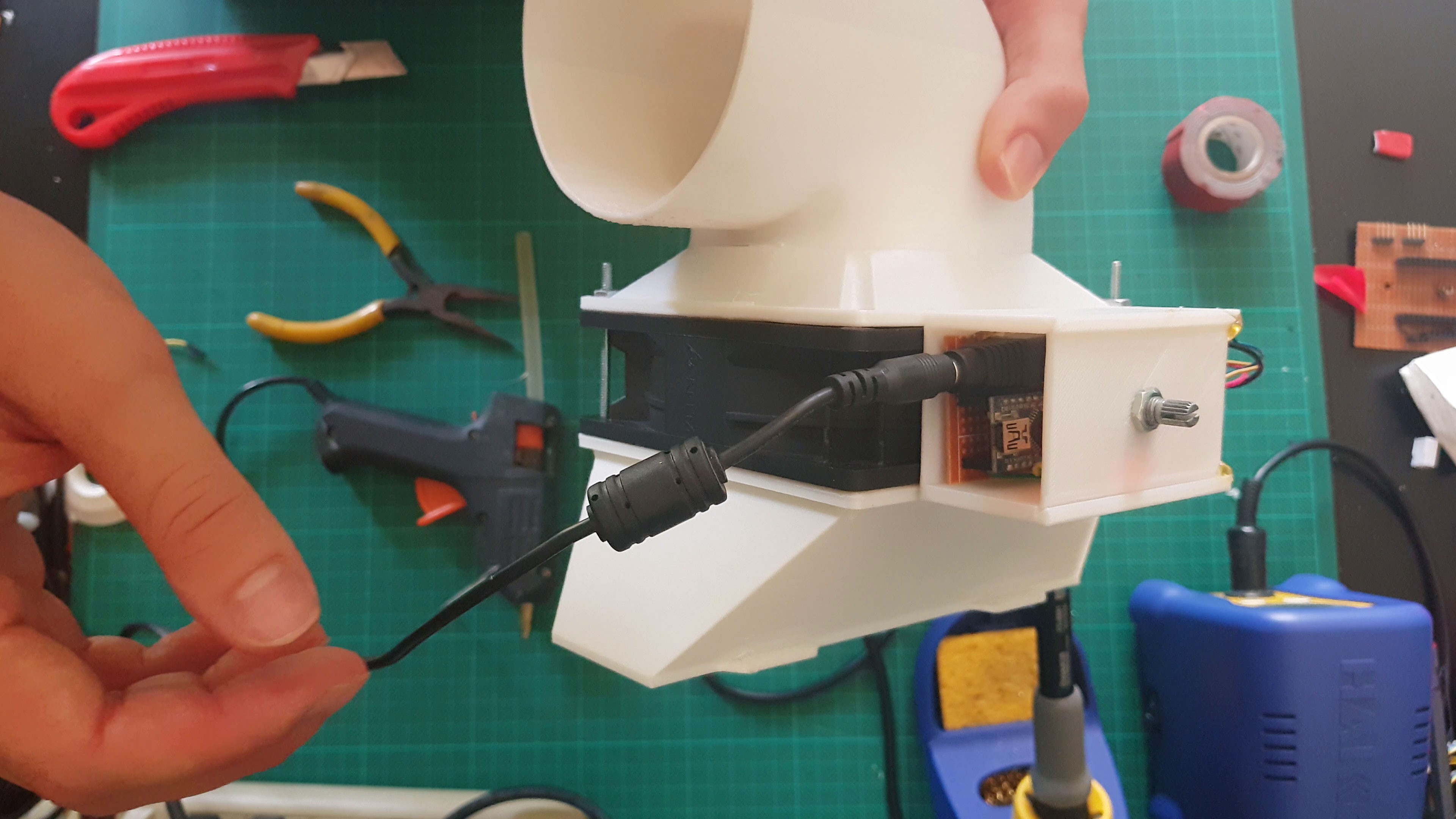
And just like that this project is complete. Looking back we managed to hit all design goals for this particular hack for the k40 laser cutter. But we are not done yet with this machine, we still have a lot to fix!
If you liked this project, feel free to check out my other project where we are building a Wi-Fi enabled visual doorbell system. The next log will be out soon.
I’ll see you then!
Discussions
Become a Hackaday.io Member
Create an account to leave a comment. Already have an account? Log In.
Looks great! Printed the stls and I am awaiting the fan. Why bother with the PWM - why not run full throttle? I cut plexiglass and need the extraction of this 250 cfm!! Thanks again... please let me know if I need a pwm.
Phil
Are you sure? yes | no