I have squeezed some simple instructions into a 16-byte ROM that writes 0x04 into the I/O address 0x00, and repeats (http://www.homebrew8088.com/):
A:
MOV AL, 04
OUT 00, AL
JMP A
This is then converted into machine code (https://defuse.ca/online-x86-assembler.htm), and I write this in the *.mem file that the Quartus 2 can deploy into the array (https://timetoexplore.net/blog/initialize-memory-in-verilog):
module storageReadOnly(output [7:0] data, input [19:0] addr, input RD);

reg [7:0] memory16bytes [16:0];

initial $readmemh("rom_image.mem", memory16bytes);

assign data = memory16bytes[addr & 20'h0000f];

endmodule
The "rom_image.mem":
B0 04 E6 00 EB FA
And here it runs:
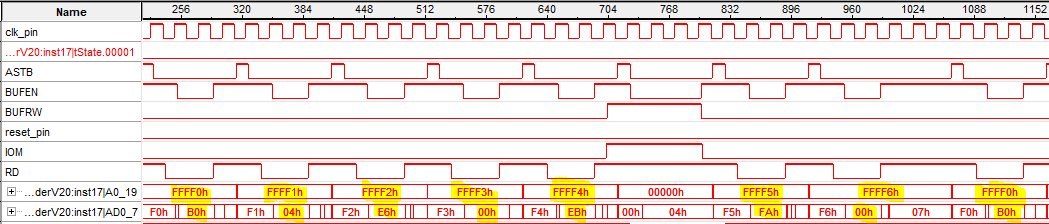
However, the decoding part isn't the most straightforward thing to write in Verilog. I'm not even sure if my version of decoding could work:
always @(negedge ASTB) begin
	if(A0_19 >= 20'hffff0 && A0_19 <= 20'hfffff)
		CS_IO_1 <= 1'b1;
	else
		CS_IO_1 <= 1'b0;
end
This CS_IO_1 is a temporary chip-select to select an I/O address which I will connect these to the LEDs later to verify the operation. I'll expand on the V20 writing to the FPGA after this.
Discussions
Become a Hackaday.io Member
Create an account to leave a comment. Already have an account? Log In.