 Gabriel D'Espindula
Introduction
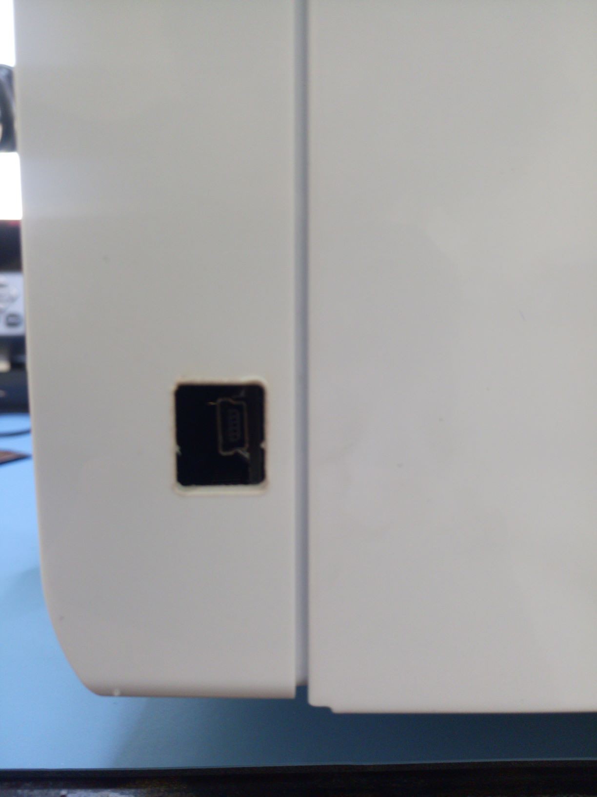
Believe you or not, I've used a brand new microwave to do this. I've looked for the cheapest option with numeric digital keyboard and display I could find in UAE and got this model:
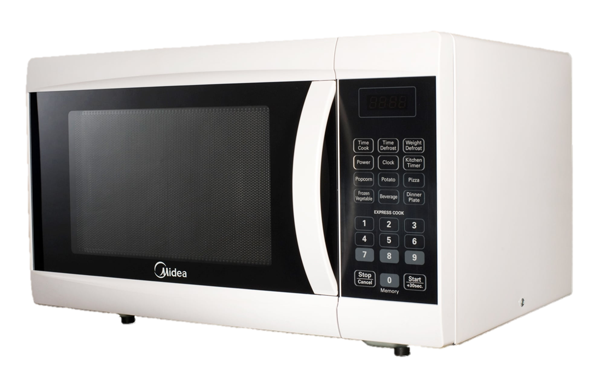
Honestly I never heard of this brand before, but the model was perfect for me!
First step was opening the machine. Second step was trying to understand how it works.
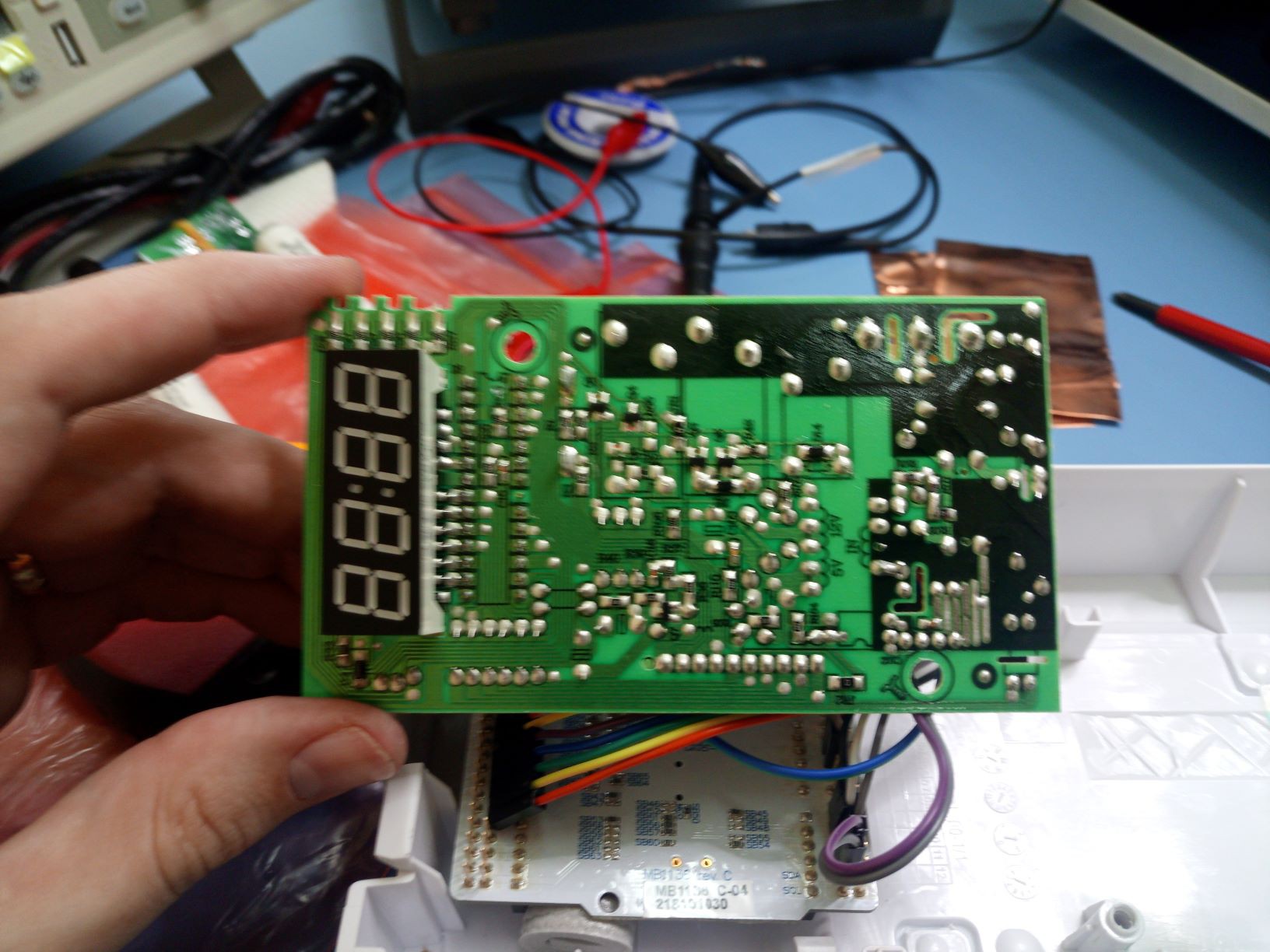
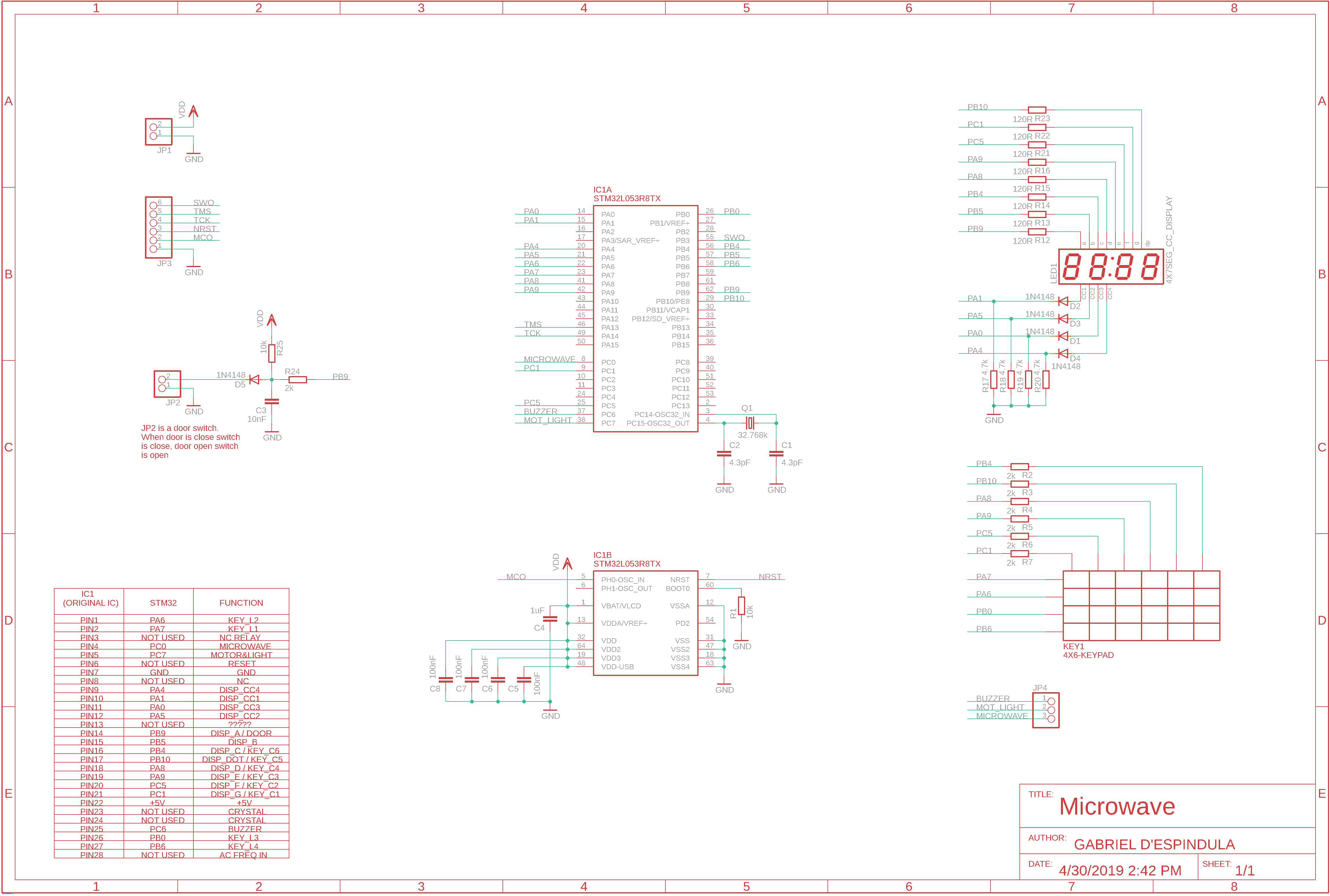
I didn't try to find the schematics online, tried to understand the circuit by myself (not really difficult, right?) and I got really surprised how fun it is! It has several hardware safety features. I'll talk about them one by one, but let's start by what I've found in the microcontroller's pinout:
| IC1 pin | Function |
| 1 | Keyboard line 2 |
| 2 | Keyboard line 1 |
| 3 | NC relay |
| 4 | Microwave generator relay |
| 5 | Motor and light relay |
| 6 | Reset |
| 7 | GND (Vss) |
| 8 | NC |
| 9 | Display CC4 |
| 10 | Display CC1 |
| 11 | Display CC3 |
| 12 | Display CC2 |
| 13 | ???? I have no idea what it does |
| 14 | Display segment A / Door |
| 15 | Display segment B |
| 16 | Display segment C / Keyboard column 6 |
| 17 | Display segment DOT / Keyboard column 5 |
| 18 | Display segment D / Keyboard column 4 |
| 19 | Display segment E / Keyboard column 3 |
| 20 | Display segment F / Keyboard column 2 |
| 21 | Display segment G / Keyboard column 1 |
| 22 | +5V (Vdd) |
| 23 | 4MHz Crystal |
| 24 | 4MHz Crystal |
| 25 | Buzzer |
| 26 | Keyboard line 3 |
| 27 | Keyboard line 4 |
| 28 | AC frequency in |
Of course the part number was scratched, and I couldn't figure out what is this microcontroller considering Vdd, Vss, reset and crystal. If you know, make a comment!
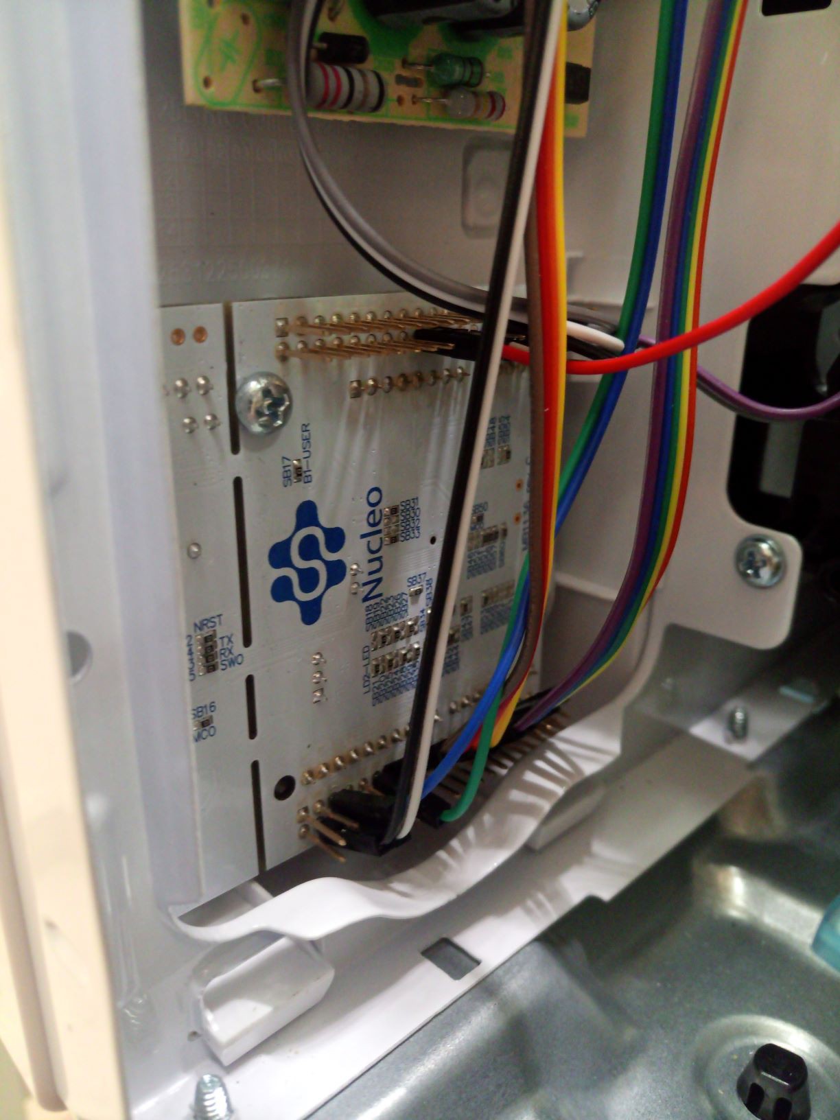
Anyway, as my goal was to substitute the uC, I didn't spend much time searching for that.
Fun solutions found
One by one I'll point all features I noticed and liked. For some of them I'm not sure about the real reason but I'll raise some possibilities, if you know the actual reason put in the comments!
Shared pins: The first nice feature was that most segments (anode pin) share pin with the keypad. While I was capturing the schematics and saw this I was very excited to alternate between inputs and outputs to make it work (as the code bellow). As @Ken Yap remarked in the comments bellow, it's not necessary to do so. Even being some obvious option to reduce pins I never thought about it when doing my own designs.
My solution in the firmware was creating a postscale inside the timer interruption handler with 5 steps as the quote bellow:
switch(postscale%5){
    case 0:
        print7seg(display[0]);
        setApin(OUTPUT);
        DS1(0);
        break;
    case 1:
        DS1(1);
        print7seg(display[1]);
        DS2(0);
        break;
    case 2:
        DS2(1);
        print7seg(display[2]);
        DS3(0);
        break;
    case 3:
        DS3(1);
        print7seg(display[3]);
        DS4(0);
        break;
    case 4:
        DS4(1);
        last_key=key;
        key=readKey();
        setApin(INPUT);
        door=HAL_GPIO_ReadPin(DOOR_PORT,DOOR_PIN);
        break;
}
postscale++;
Buzzer: This was one of my favorite things. The buzzer doesn't have an internal oscillator, and is possible to use it as a polyphonic speaker. I didn't implement that, but the fist thing came to my mind was a super mario themed microwave hahaha every key...
Read more »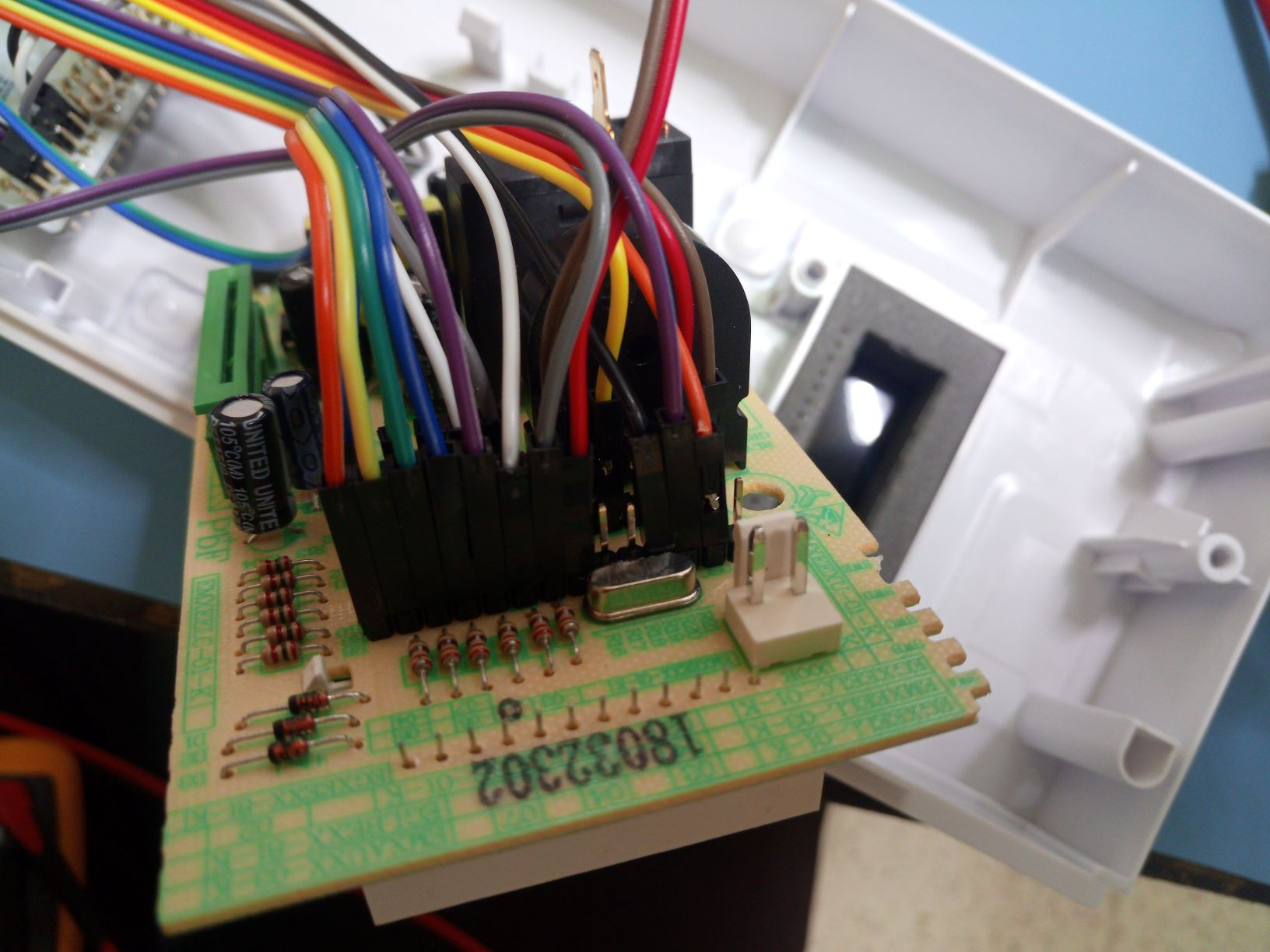


 thpoll
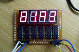
 HummusPrince
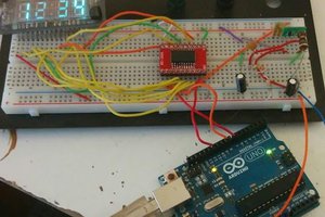
 Brad Arnett
 Ian Norton
Your creativity knows no bounds! Keep up the fantastic work.
https://ptliga.fans/