0%
0%
Open Source Light and Motion Controller
The goal of this project is to develop an open-source firmware and controller for kinetic sculptures, mobiles and moving lamps.
 marciot
Become a Hackaday.io member
Already have an account? Log in.
Just one more thing
To make the experience fit your profile, pick a username and tell us what interests you.
Pick an awesome username
hackaday.io/
Your profile's URL: hackaday.io/username. Max 25 alphanumeric characters.
Pick a few interests
Projects that share your interests
People that share your interests


 DigiGram
 CriptasticHacker
 terrag
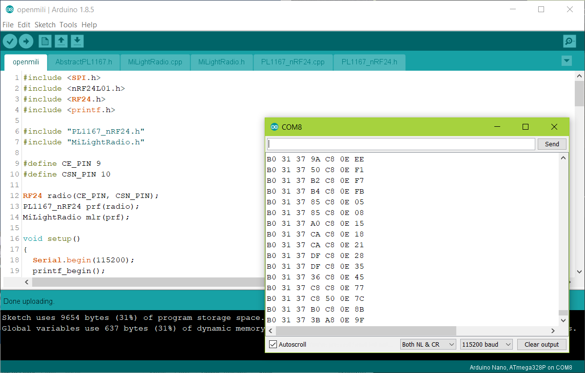
Take a look: at https://github.com/komby/RFShowControl
Basically extends DMX512 to run via NRF24 modules, and has some useful demo code for things like direct PWM and such.
DMX plus something like Q Light Controller Plus allows you to program full shows, open source. A real (not a clone) FTDI chip also shows up in QLCP as a DMX device (as someone used it for one) and so if you have some NRF24 modules, an Arduino, and a FTDI programmer, you actually have an RFShowControl transmitter already.