 Just4Fun
* * HARDWARE OVERVIEW * *
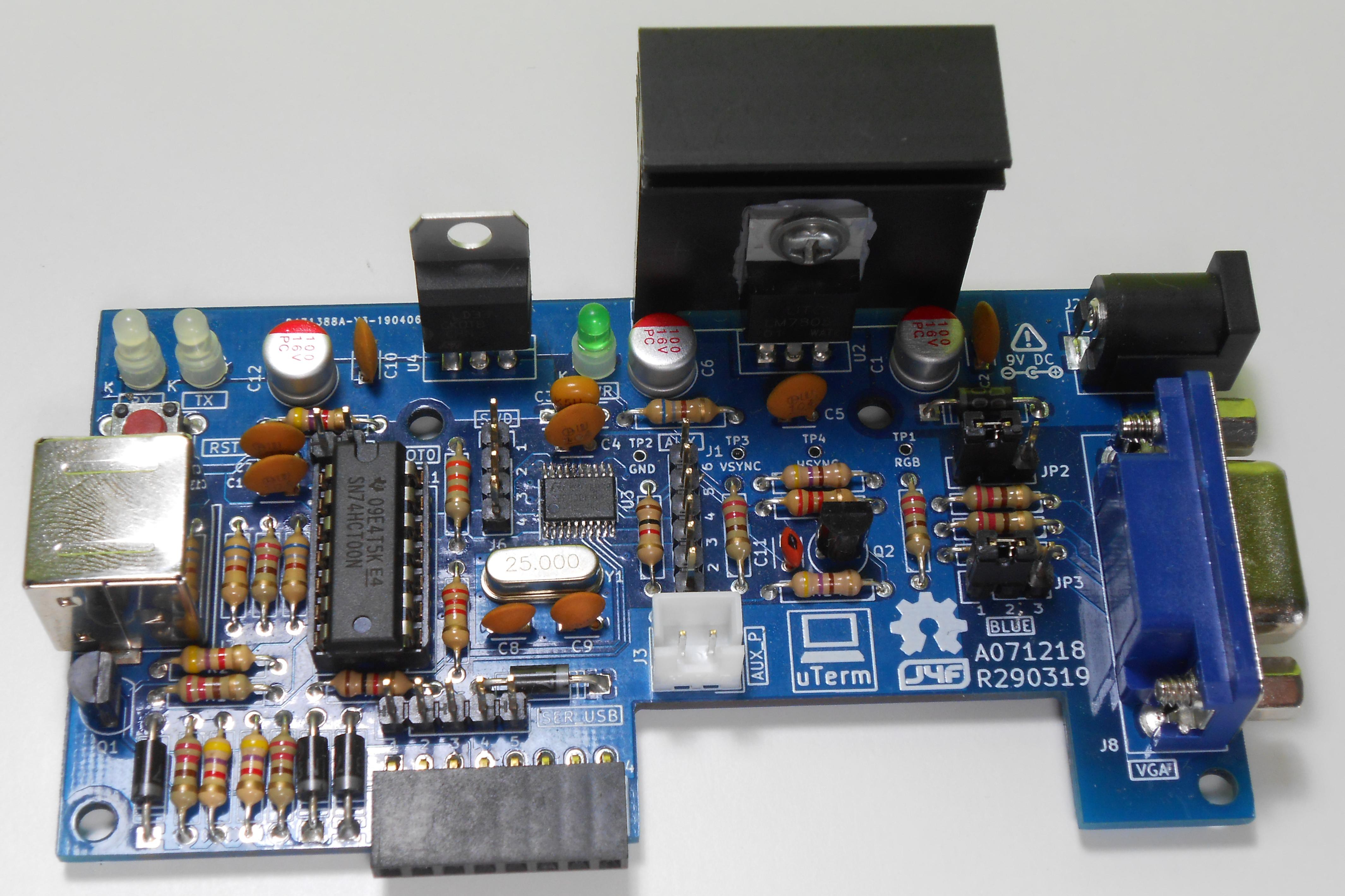
uTerm is an add-on card for the Z80-MBC2 single board computer to add a VT100-like terminal, a power supply and a "transparent" serial-USB port for a serial-USB adapter.
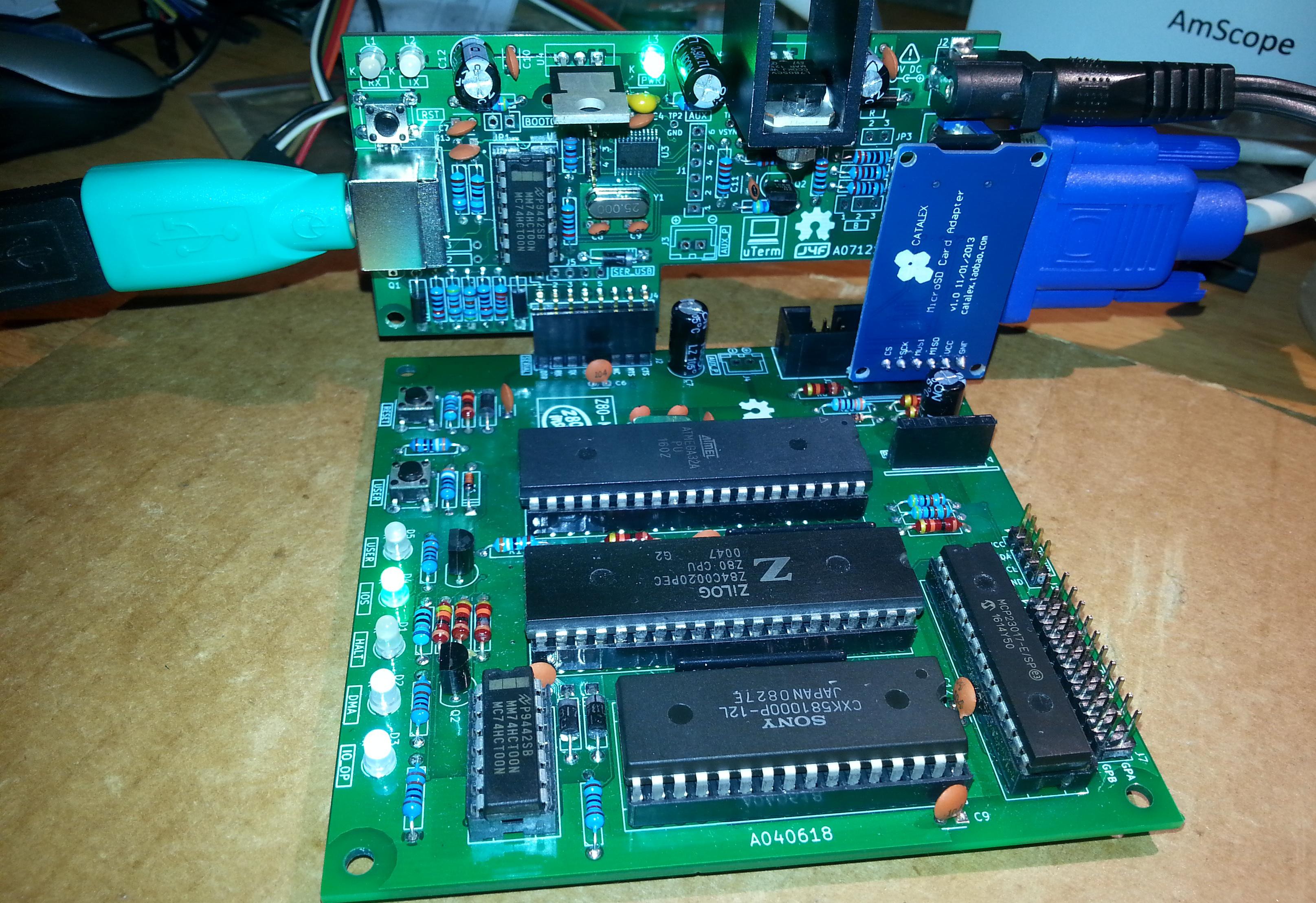
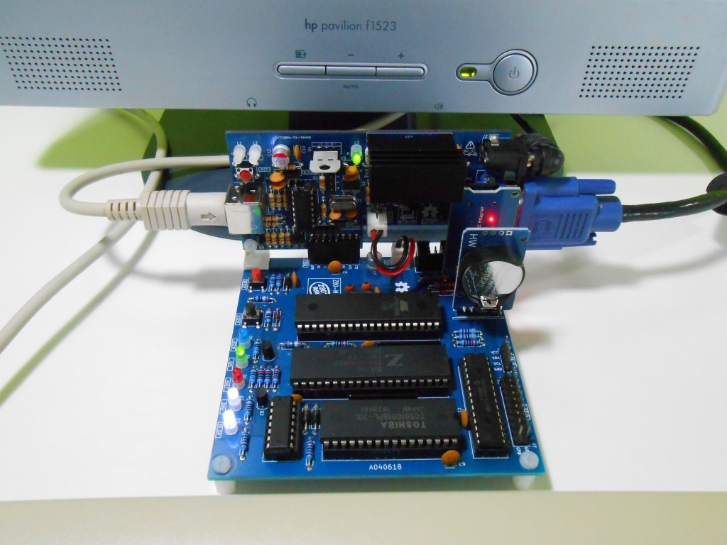
Here a previous version of uTerm vertically inserted into the Z80-MBC2 board:
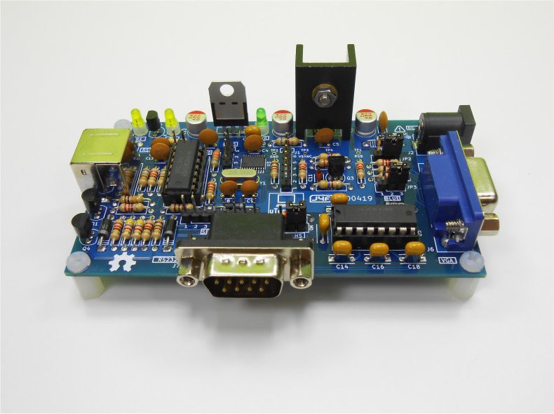
and here assembled horizontally:
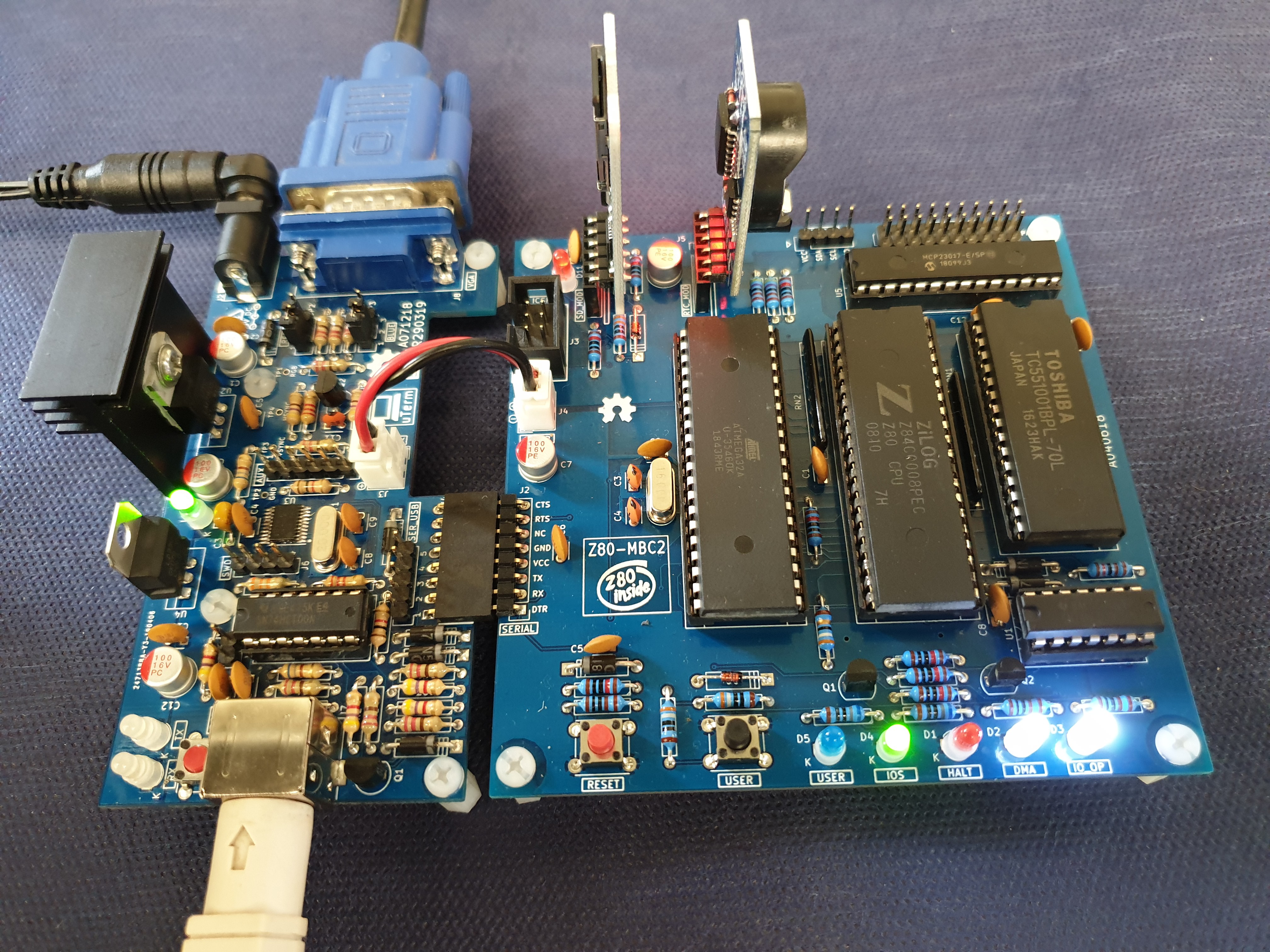
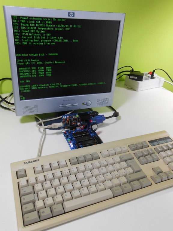
With the uTerm the Z80-MBC2 becomes an "autonomous" computer: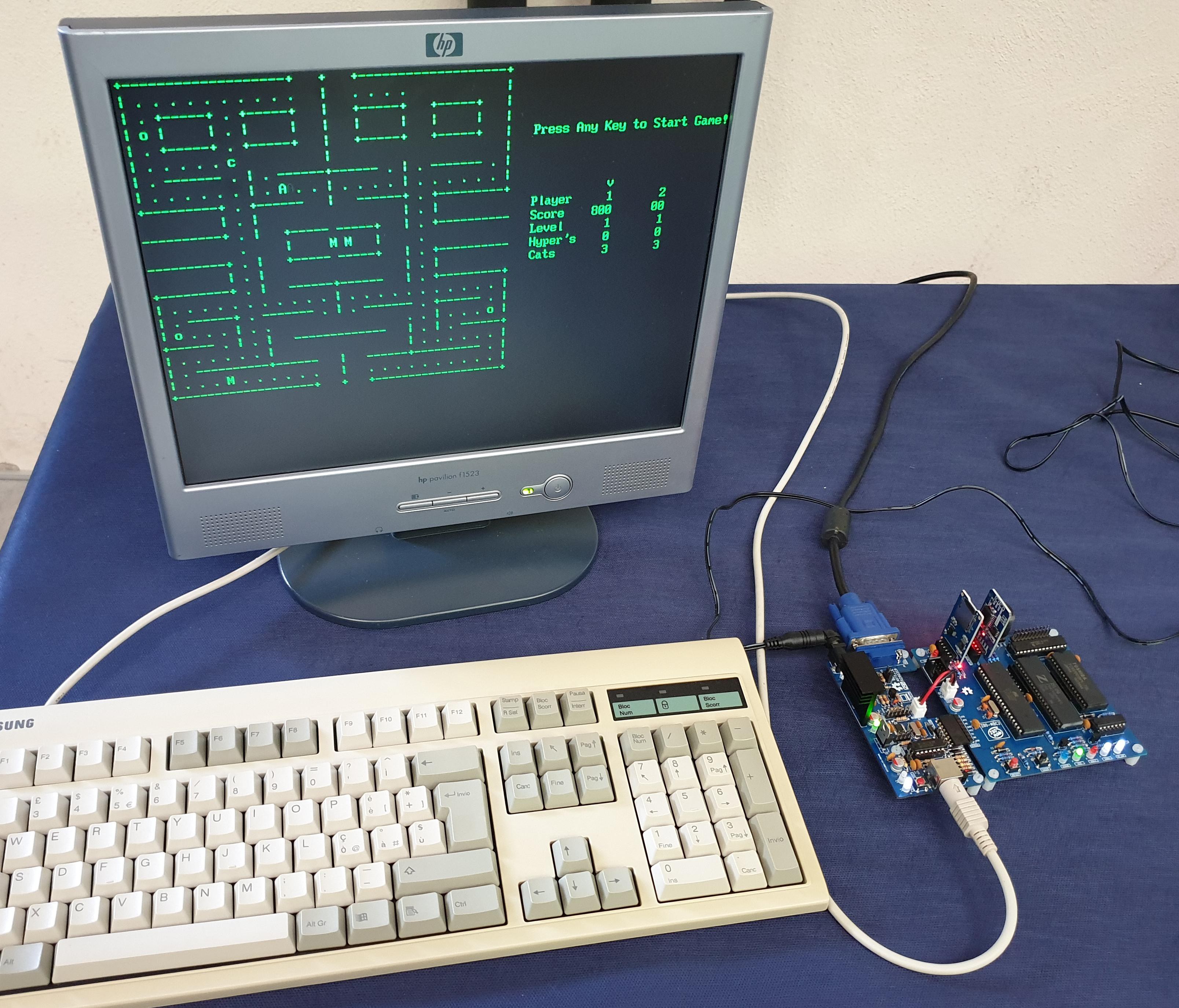
A couple of videos running "famous" CP/M games:
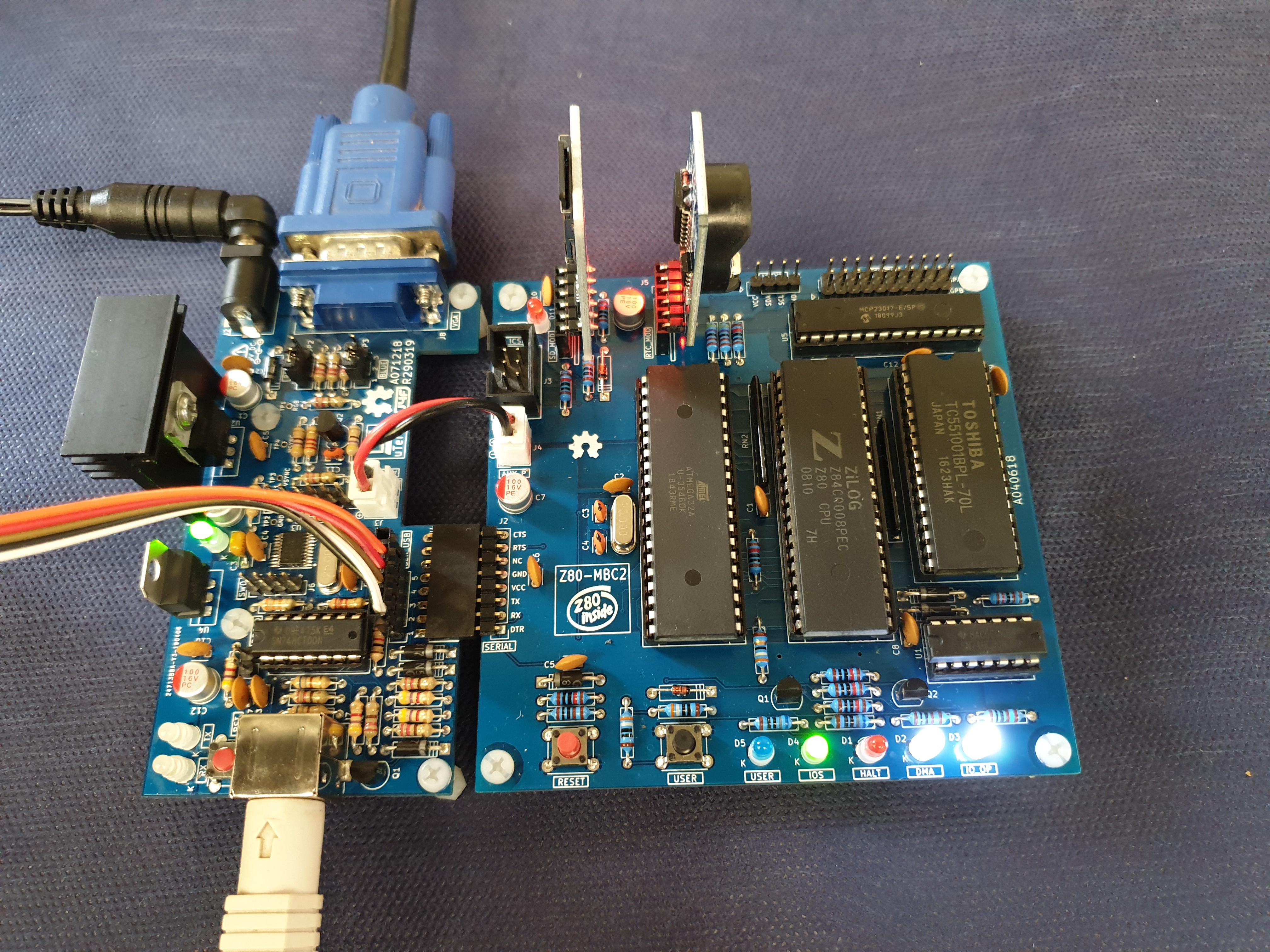
THE "TRANSPARENT" SER_USB PORT (J5)
The uTerm has a "transparent" USB-serial adapter connector, so you can upload firmware to the Z80-MBC2 (using Arduino IDE) or load an Intel-Hex file (with iLoad) or use XMODEM to exchange files with a PC (running a terminal emulator that supports XMODEM file transfer) while the uTerm is in use.
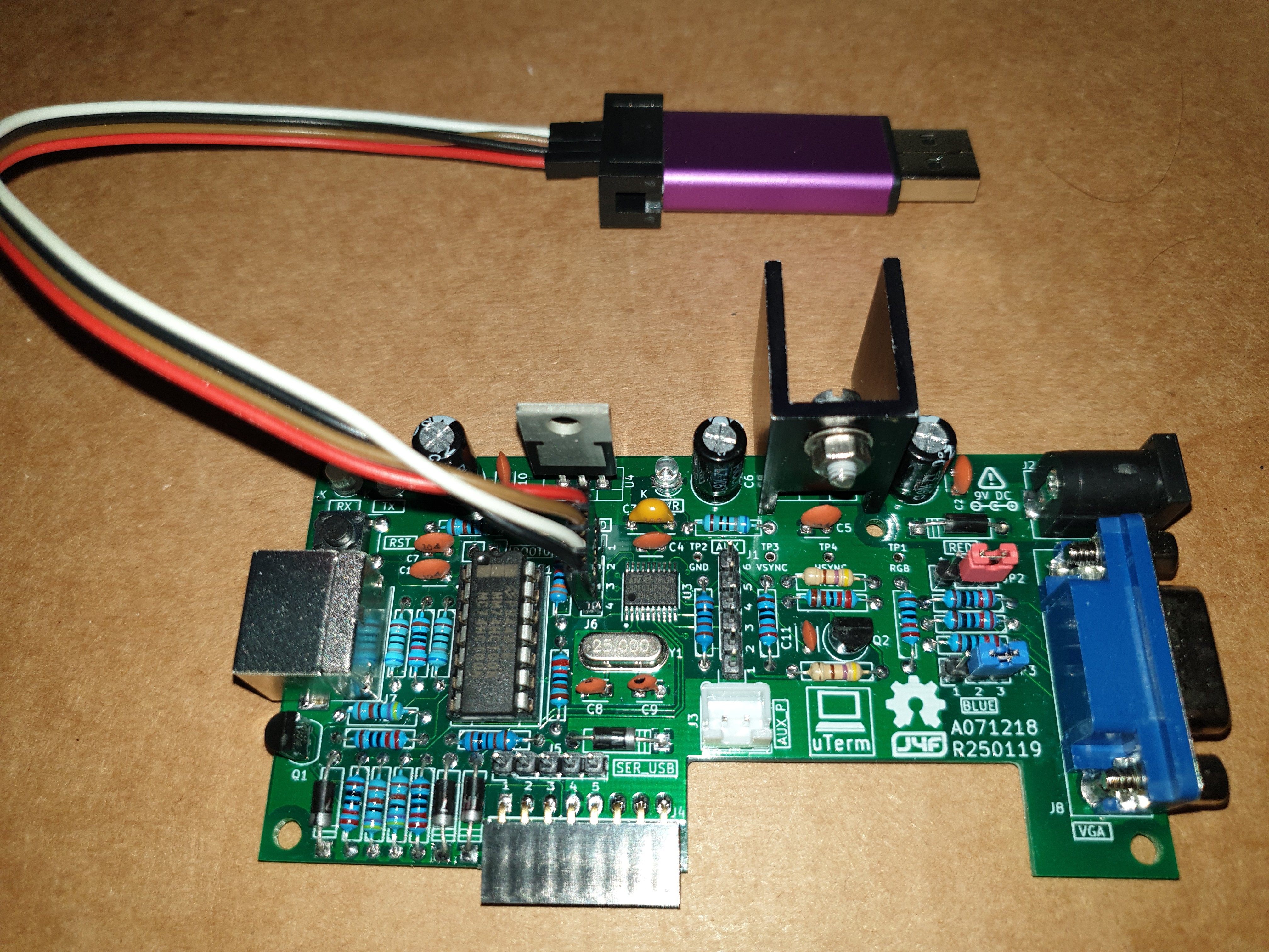
Both the "mixed" power supply scenarios (USB-serial adapter not powered from USB but Z80-MBC2 powered and vice-versa) are managed by the HW, so you don't need to worry about it. In the following photo a serial-USB adapter is connected with a cable to the transparent SER_USB port:
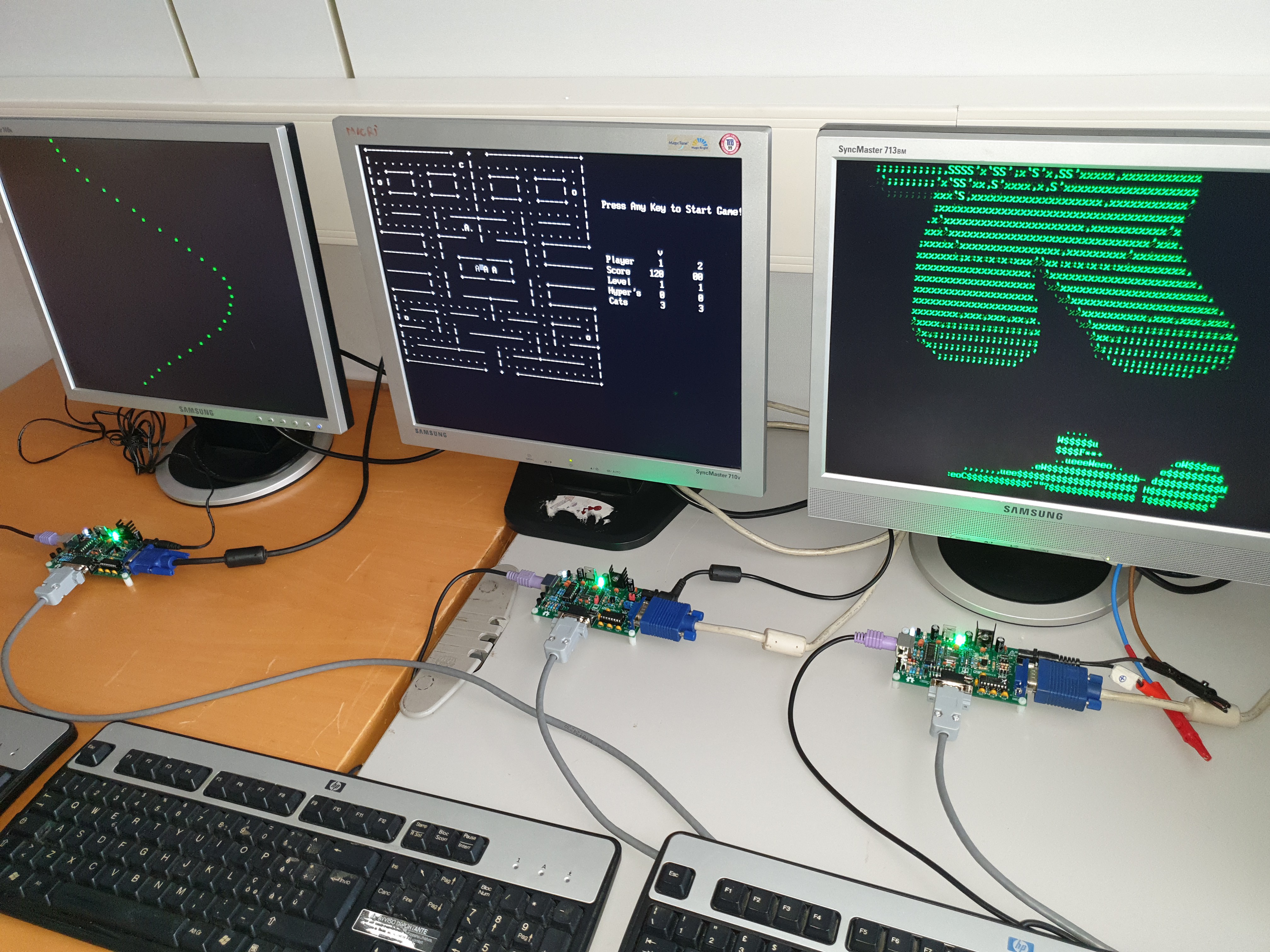
This allows to use two keyboards and two monitors in the "same" time (one keyboard and monitor attached directly to the uTerm, and another keyboard and monitor of the terminal emulator on a PC connected with the serial-USB).
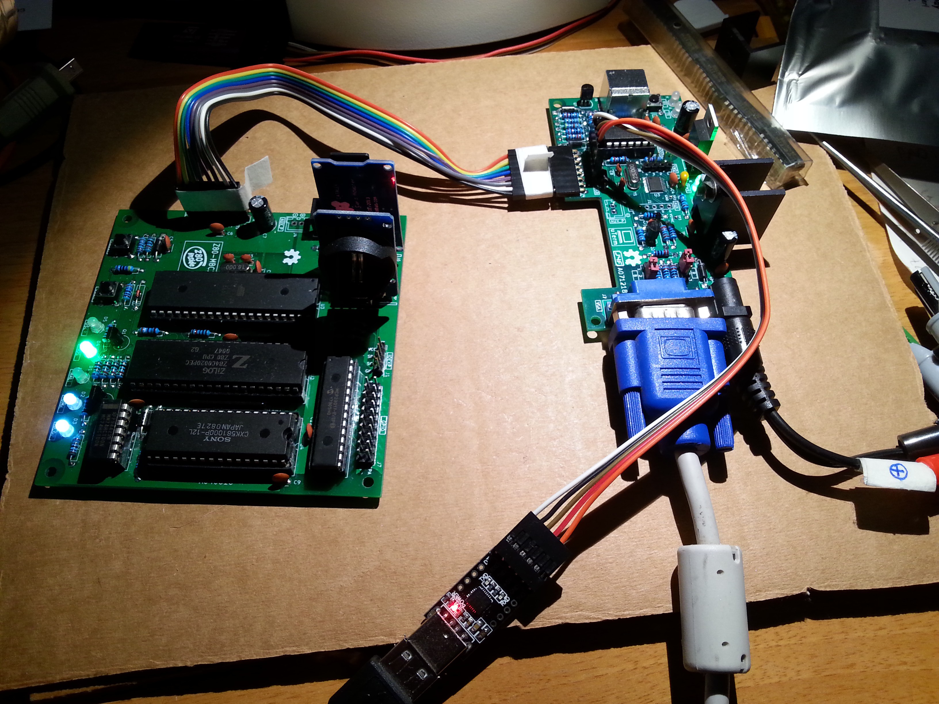
Or you can use the monitor attached to the uTerm and the keyboard of the terminal emulator on a PC. This is exactly the "configuration" I used in the following photo. As you can see, there isn't any keyboard attached to the uTerm (previous version attached to the Z80-MBC2 with a cable):
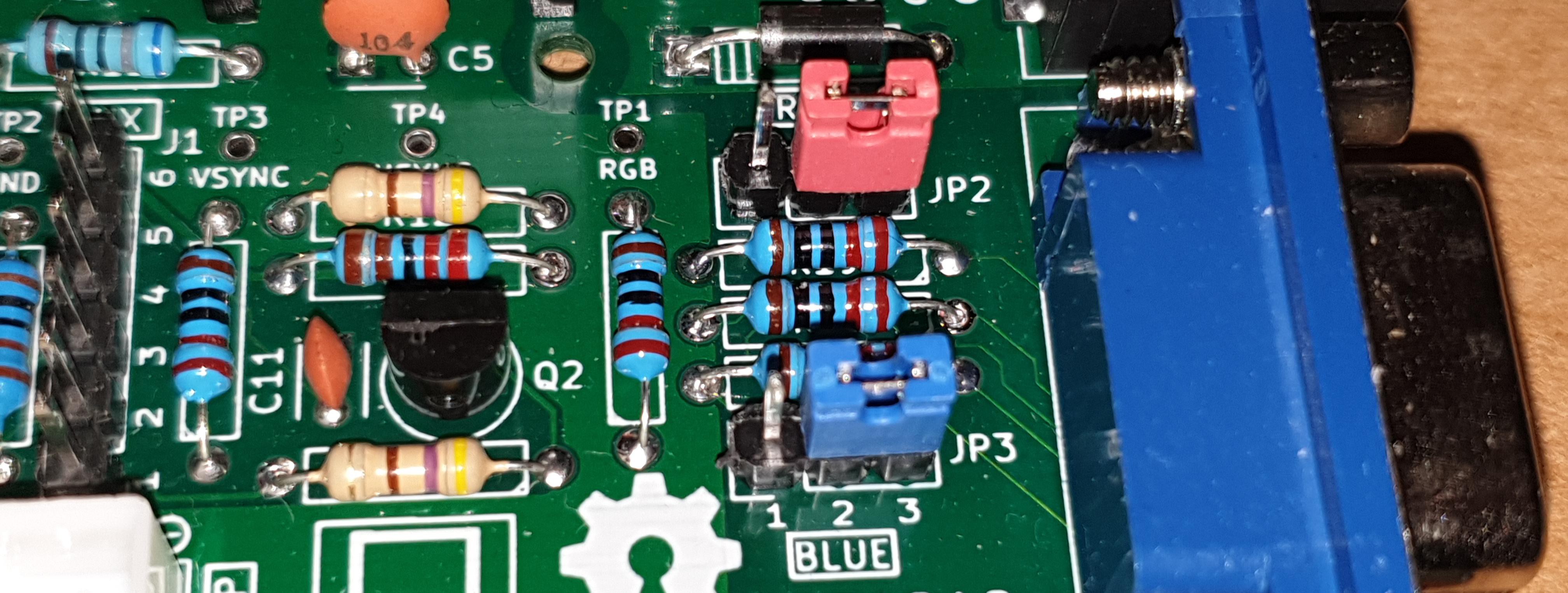
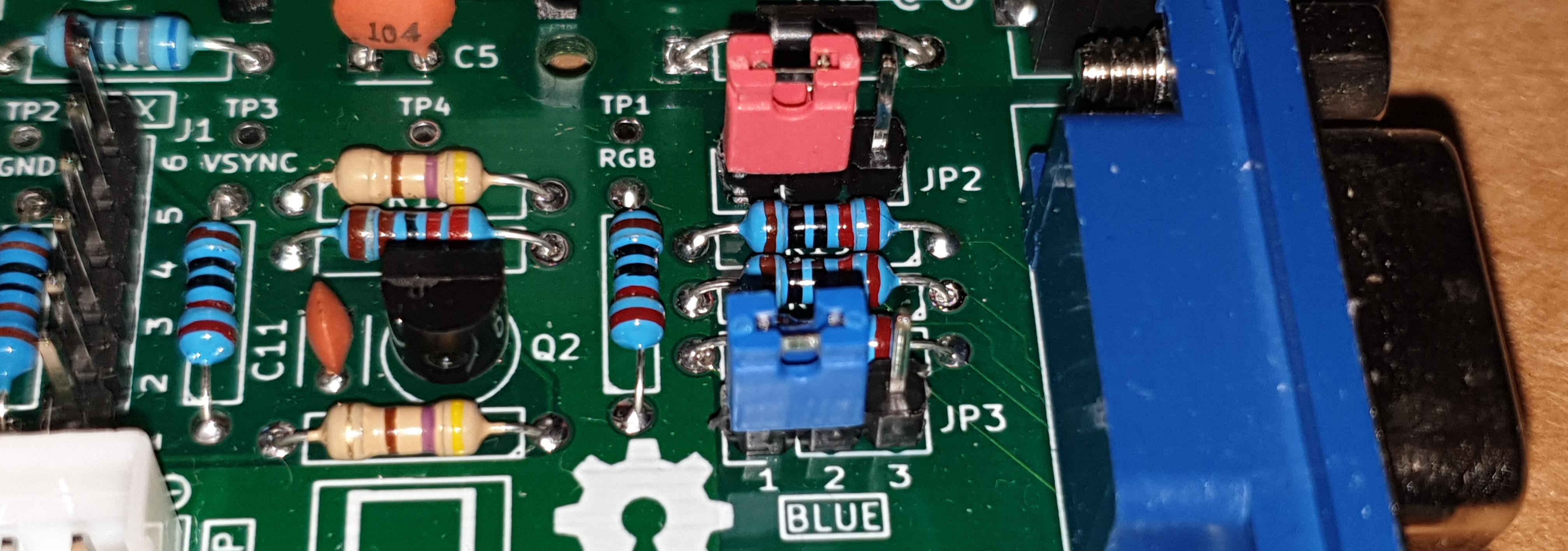
CHANGING THE COLOR (JP2-JP3)
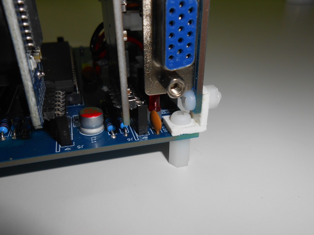
It is possible choose among 4 colors (green, white, cyan, amber) for the output VGA signal. To select the color use the JP2 and JP3 jumpers. In the following photos are shown the setting for JP2 and JP3 to select the color as white or green respectively:
THE AUX_P CONNECTOR (J3)
This connector is intended for a better power supply connection for the Z80-MBC2. The use of this connector is recommended only if the uTerm and the Z80-MBC2 are connected with a cable. If they are directly connected (vertically or horizontally) the use of J3 is optional.
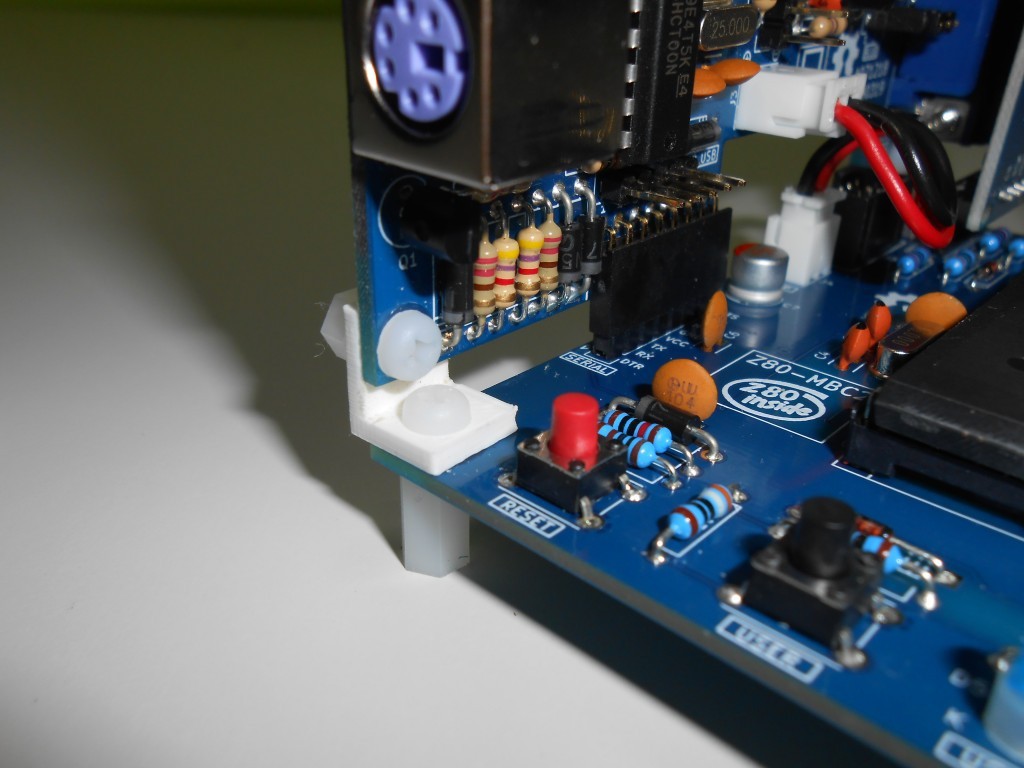
CUSTOM 3D PRINTED ANGLED BRACKETS
For a solid vertical mounting two 3D printed angled brackets have been created:

Please note that the left and the right angled bracket are different:
The .STL files are in the Files section.
CUSTOM 3D PRINTED STRAIGHT BRACKETS
For a solid horizontal mounting two 3D printed straight brackets have been created:

The .STL files are in the Files section.
* * SOFTWARE OVERVIEW * *
uTerm is based on the ChibiTerm (https://hw-by-design.blogspot.com/2018/07/low-cost-vga-terminal-module-project.html), and the original software was modified to avoid any "interference" using the "transparent" serial-USB port.
The FW is available as source or a binary file ready to be flashed into the STM32. The source files are in the linked repository on Github. The binary file ready to upload is in the Files section.
uTerm serial is set to 115200 baud to meet the speed of the Z80-MBC2 with the current IOS revision. Only the US keyboard is supported. It has a 80 columns x 30 rows screen.
HOW TO FLASH THE STM32 WITH THE ST-LINK V2
In the following we'll see how to flash the (executable .bin) binary file into the STM32 MCU using a ST-link V2 programmer.
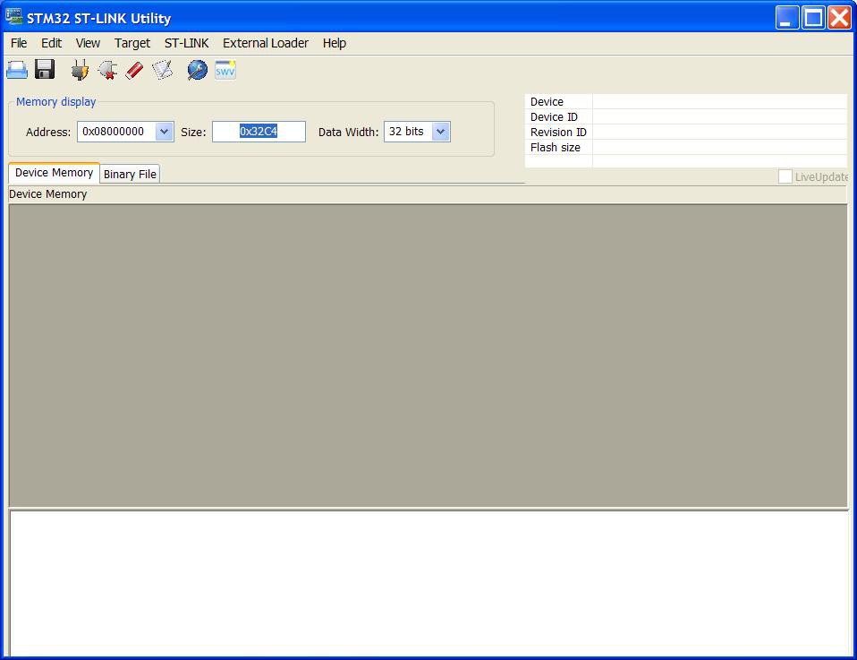
The first thing you need is the STM32 ST-LINK Utility (STSW-LINK004) utility. You must download it from here (a registration may be required).
Install the utility and execute it. When you execute it without the ST-Link V2 programmer connected this is the output:
Now is time to use the ST-Link V2.
* * WARNING!! * *: Before to connect the ST-Link V2 to the uTerm, check carefully that the uTerm is not powered and not connected to anything else!
Always connect before the ST-Link V2 to the uTerm and then connect it to the USB!
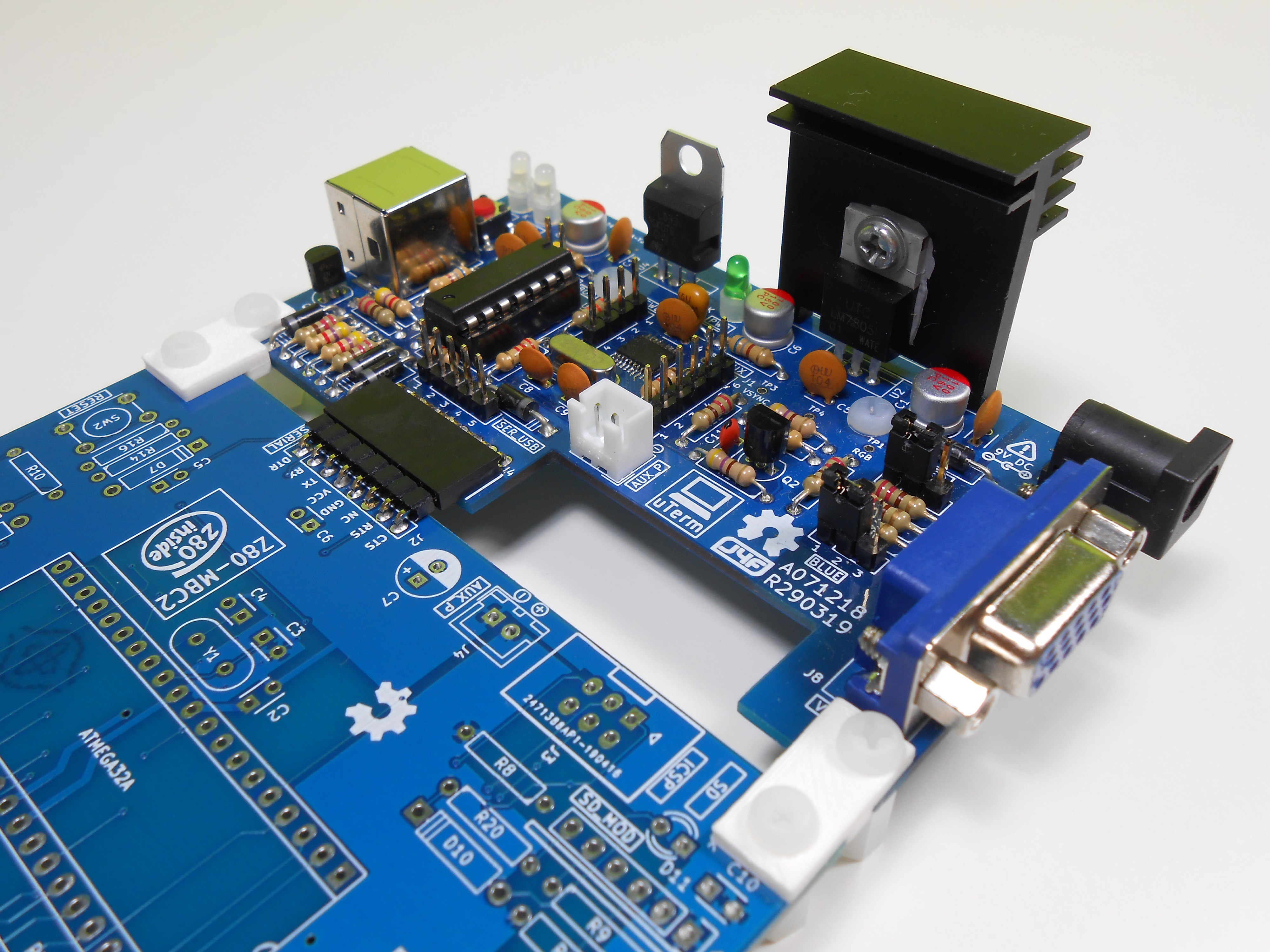
Connect the ST-Link V2 to the uTerm using the pins SWCLK, SWDIO, GND, 3.3V to the corresponding pins of the SWD connector (J6) of the uTerm board.
* * WARNING!! * *: When connecting the ST-Link-V2 to the uTerm, pay attention to use the 3.3V pin to source the power and not the 5V pin!!!
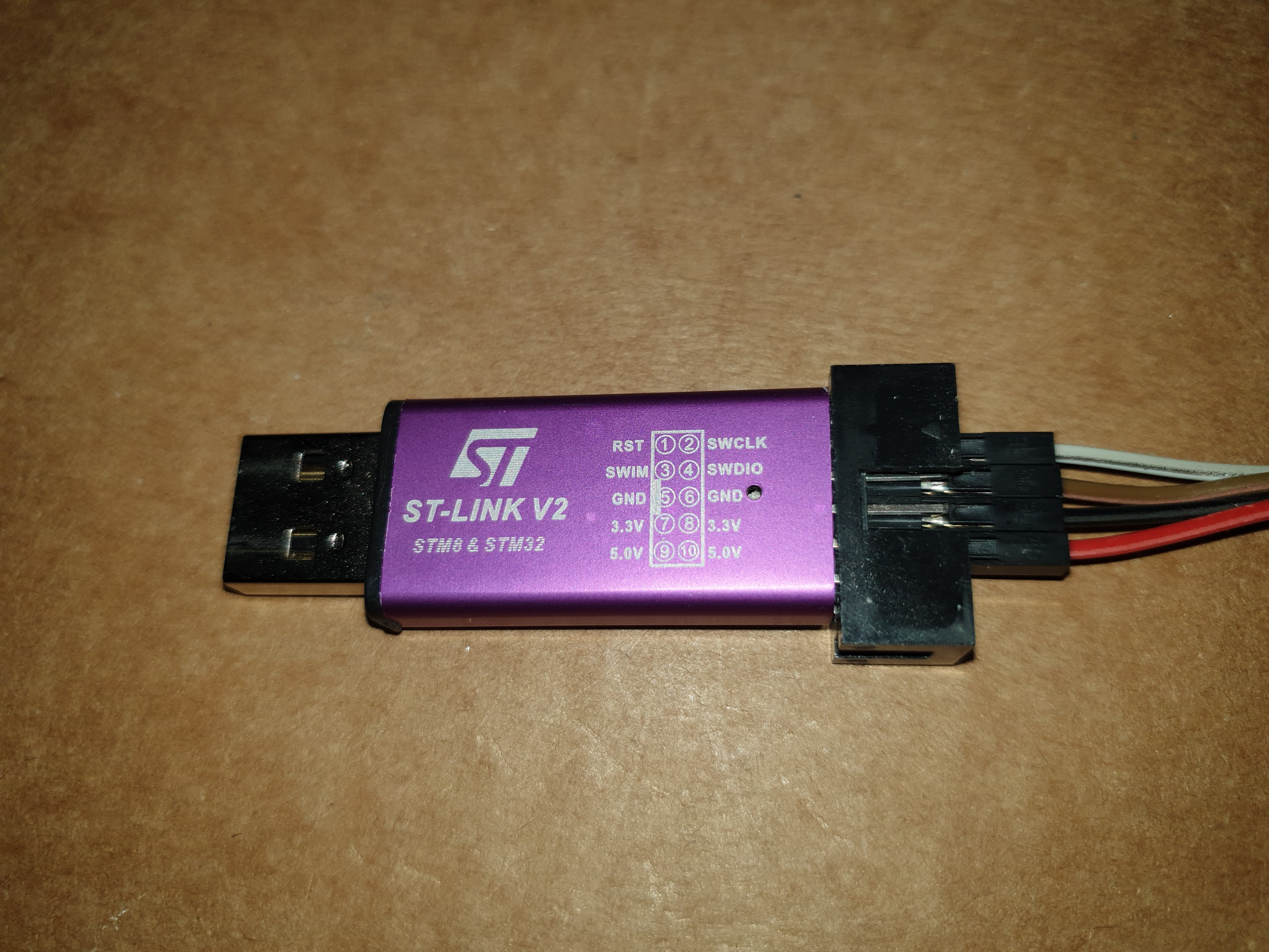
Please note that some ST-Link V2 may have a different pin placement! So check carefully yours using the printed layout:
In the following photo there is a ST-Link V2 connected to the uTerm (previous version):
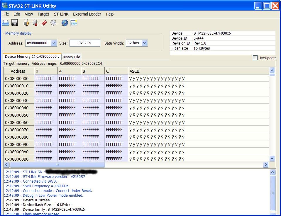
 When the ST-Link V2 is connected to the USB of your workstation re-execute the STM32 ST-LINK Utility. Go to the Target -> Connect menu of the STM32 ST-LINK Utility. The following situation will appear for a "blank" STM32:
Go to Target -> Settings and check that you have the same settings (the Frequency setting may be different because I have lowered it using a VM):

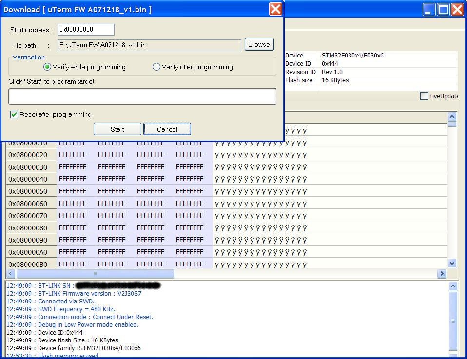
After that go to Target -> Program & Verify, select the binary file to flash and press the Start button (verify before that Verify while Programming is checked):
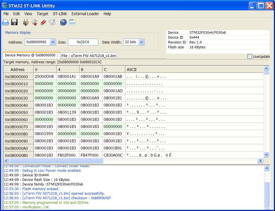
When finished it will be possible to see the green message of the successful write and verification in the bottom of the window:
All done! Disconnect the ST-Link V2 from USB first and than disconnect it form the uTerm.
To do a first check just connect the VGA (J8) to a monitor and the power input DC-IN (J2) to a 9V DC source. A blinking cursor should appear in the upper left of the monitor.
* * STAND-ALONE VERSION (UTERM-S) * *
I've made a "stand-alone" version (uTerm-S) with a RS232 port, so it is a VT100-like RS232 terminal (just adding a VGA monitor, a PS/2 keyboard and a 9V power supply):
For more information see here.
* * HOW TO GET A PCB * *
I've prepared an "easy link" to order a small lot (min. 5 pcs) of PCB here.
* * HOW TO GET A KIT OR AN ASSEMBLED UNIT * *
If you are looking for a kit with all the needed parts (including the 3D printed parts) or an assembled unit ready to use there is a professional seller that can sell both and ship worldwide.
The link to the seller is this one.
* * CREDITS & LICENSE * *
The video terminal is based on the ChibiTerm by K. C. Lee (https://hw-by-design.blogspot.com/2018/07/low-cost-vga-terminal-module-project.html).
VT100 emulation was added by Madis Kaal (http://www.nomad.ee/micros/chibiterm.shtml).
Thanks to gkaufman of the Retrobrew Computer Forum for a bug that has been discovered and solved by him.
All the project files are licensed under GPL v3.