This project is sponsored by LCSC. I have been using electronic components from LCSC.com. LCSC has a strong commitment to offering a wide selection of genuine, high quality electronic components at best price. Sign up today and get $8 off on your first order.
Adding power supply to the Arduino
The Arduino power jack can accept an input voltage range of 7 to 16 volts. The most common input sources are a trusty 9V battery or a 9-12VDC power supply. Because most sensors and chips require a 5V source, we will need the LM7805 voltage regulator to cut the 9V down to a component friendly 5V. If you connect more than 16V, you risk damaging the IC.
- Add power and ground wires for where your voltage regulator will be.
- Add power and ground wires at the bottom of your board connecting each rail.
- Now, add LM7805 regulator to the breadboard. It will take input of 9V and gives out a continuous supply of 5V from the output.
- Add power OUT and ground wires that connect to the right and left rails of the breadboard.
- Also, add a 10uF capacitor between the IN of the regulator and the ground as well as a 10uF capacitor on the right rail between power and ground. The silver strip on the capacitor signifies the ground leg.
- Place the power LED close to the input source and at the top of the breadboard. You can use the green or red LED. Connect a jumper wire from the negative lead (short leg) of the LED to the ground rail and install a Ω resistor from the positive LED lead (long leg) to the power rail.
Adding board components
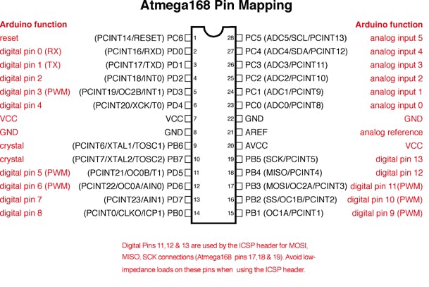
Pin mapping of ATmega328P-PU
Before moving on, check out this image. It's a great resource for learning what each of the pins on your ATmega chip do in relation to the Arduino's functions. This will clarify a lot of confusion behind why you hook up certain pins the way you do. For even more detailed information, take a peek at the datasheet for the ATmega 168 (short version) (long version). Here's the sheet for the ATmega328 (short version) (long version).
- Install the ATmega328 chip (shown on right) so the notched side of the IC is at the top. If you are mounting the components on a PCB, it is a good idea to use the socket. Add the 10KΩ pull-up resistor to the +5V rail and connect the other end to the RESET pin on the ATmega328 (pin 1). Add jumpers for power and ground for the following pins.
Pin 7 - VCC, digital supply voltage (+5V)
Pin 8 - GND (ground rail)
Pin 22 - GND (ground rail)
Pin 21 - AREF, analog reference pin for ADC (+5V)
Pin 20 - AVcc, supply voltage for the ADC (+5V)
- Add a 16 MHz external clock between pin 9 and 10, and add two 22pF capacitors running to ground from each of those pins.
- Add the momentary button as a reset switch, so it spans the gap on the breadboard the same way the IC does. Add a small jumper wire from Pin 1 of the ATmega328 to the bottom leg of the push-button (pin closest to the IC). Add another jumper wire from the top left leg of the push-button over to ground.
- Pull the chip from your working Arduino and try it on this board. The blink_led program blinks pin 13. Pin 13 on the Arduino is NOT the AVR ATMEGA8-16PU/ATMEGA168-16PU pin 13. It is actually pin 19 on the ATmega chip.
- Finally, add the LED. The long leg or the anode connects to the red wire and the short leg or the cathode connects to the 220 ohm resistor going to ground.
Uploading sketch to your Arduino
You can go here to know about the ways to upload sketch to arduino.
You will need a USB-to-Serial device. I used the FDTI Basic Breakout Board (5V). If you just want to get it working, you can skip installing the 6-pin header and just run jumper wires straight from the USB-TTL header to the appropriate pins on the breadboard. Be sure the pins are routed correctly for the serial device you choose; the pins on the breakout board are labeled with three-digit names. During my build I discovered the microcontroller needs a perfectly timed press of the reset button to ready the chip to be programmed and the breakout board has a pin called DTR/GRN which sends a signal to the reset pin when hooked up properly. So, connect a jumper wire from (DTR/GRN) on the breakout board to Pin 1 of the ATmega328 via a 0.1µF ceramic capacitor.