-
1Step 1
First, get a LED flashlight. I used the 27 led flashhlight from Harbor Freight, because it had a bright LED aray
-
2Step 2
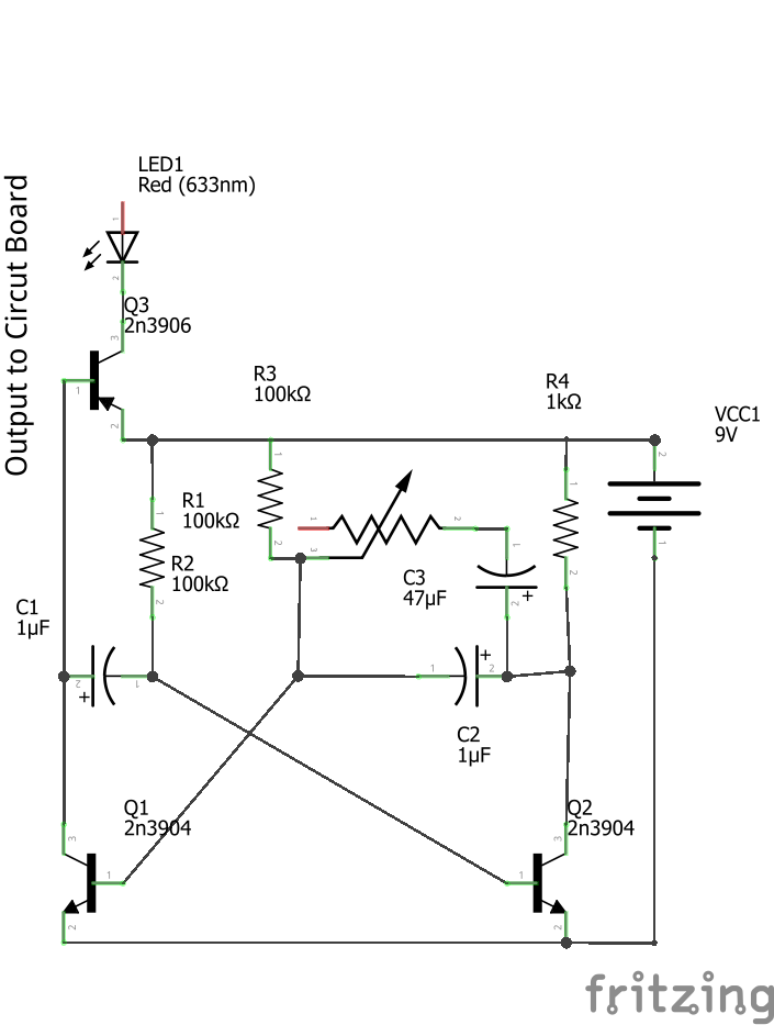
Next build the Astable multivibrator Circuit. Use leads for the Negative, Output and Potentiometer-Capacitor systems. I Dead Bug soldered everything together, so it could be bent to fit in the case.
![]() EDIT: I forgot Q3 in the first schematic I posted. I apologise if this caused any problems.
EDIT: I forgot Q3 in the first schematic I posted. I apologise if this caused any problems.NOTE: C2 sets the high flash limit. if you remove C2, you can set the strobe to be fully on.
-
3Step 3
dissasemble the flashlight to get access to the LED circut bord
-
4Step 4
Now we are going to begin modifying the circuit board.
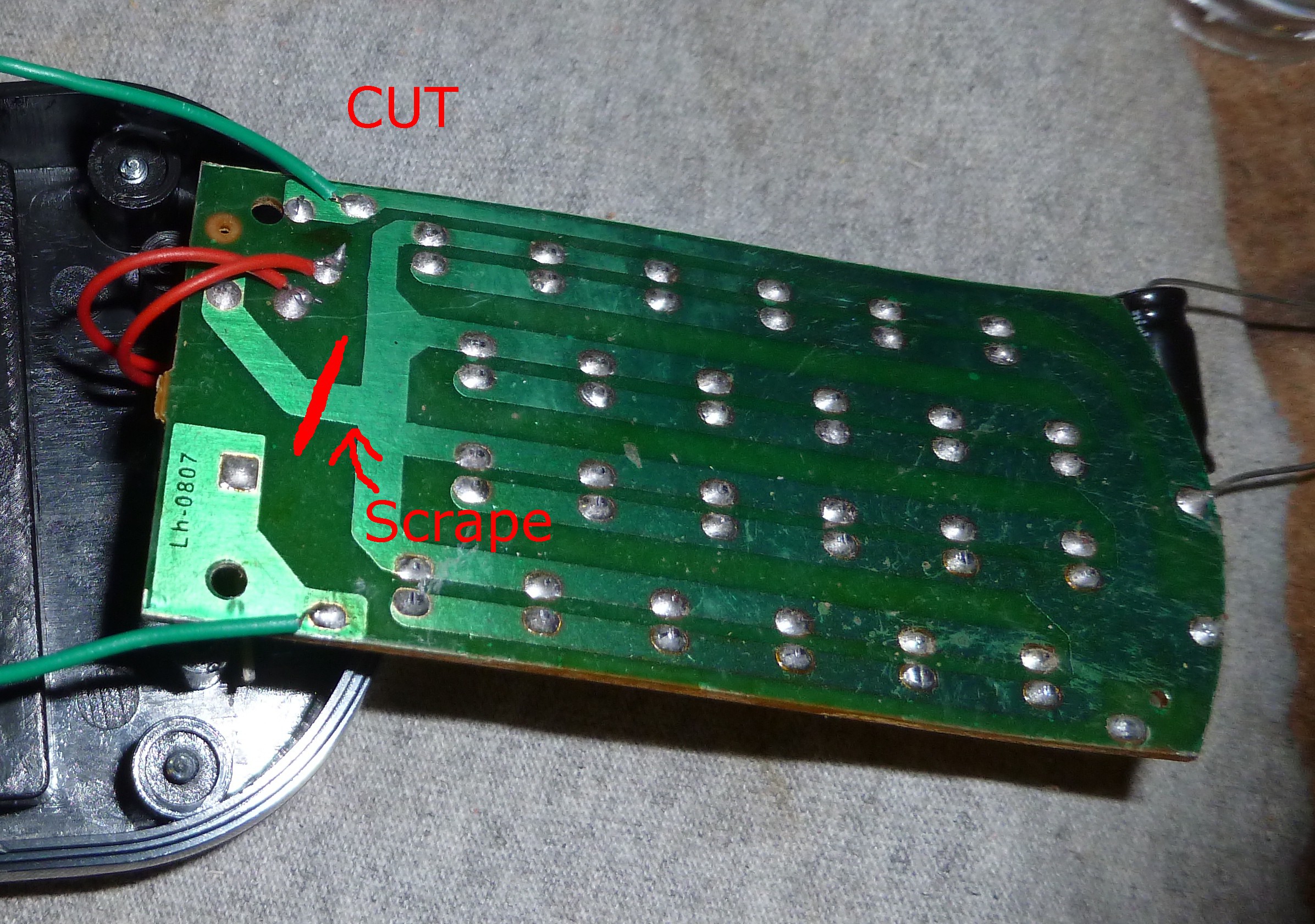
Using a knife, file, or other suitable object, you are going to cut the trace between the switch and the negative end of the large LED array. you will also want to scrape away the coating on the LED side of the array right after the cut to expose a copper pad to solder to.
![]()
you also want to disconnect the two red wires coming from the switch, and the positive wire. the two red wires go to the front LED array. the front array can be removed and discarded.
-
5Step 5
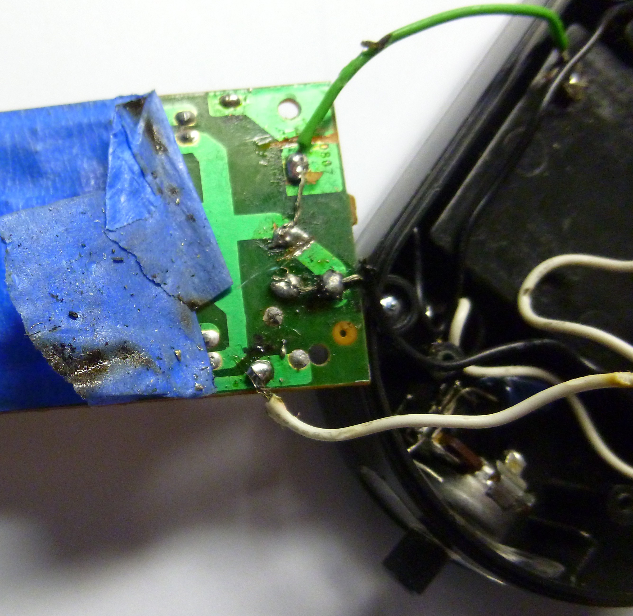
The negative wire (green) is connected to the "in" side of the switch. you will want to also connect the wire to the copper pad you just exposed. The positive wire will be connected to the positive end of the Multivibrator circuit. the negative wire from the multivibrator (black) will be connected to both of the "out" pads on the switch. the Output wire from the multivibrator (white) will be connected to the positive end of the led circuit board.
![]()
This is a picture taken after the project was completed You won't have any tape on yours.
-
6Step 6
now we will insert the control dial.
remove the clear lense from the front LED array. in this front lense, drill a hole large enough for the shaft from the potentiometer. put the potentiometer in this hole, and put it back in the light. the potentiometer I used was large enough that it didn't need any mounting materials.
-
7Step 7
carefully cram the multivibrator circuit into the case, making it as small as possible. then run the wires to the Potentiometer along side the battery bulge. then cover the back of the circuit board with a non conductive tape (I used masking tape) to prevent shorts. then put the board back over the battery bulge, replace the reflector, and reassemble the case as best as you can with the three screws you didn't loose. Your strobe should be complete and functional. If it doesn't work, check for shorts, and make shure you built the curcits correct.
-
8Step 8
NOTE:
The values used in this project are non-critical. feel free to experiment.
This project involves flashing lights. please don't build if you have epilepsy, and if you know someone with epilepsy, please don't use this strobe around them. I accept NO responsibility for problems caused by this project.
 Steel_9
 EDIT: I forgot Q3 in the first schematic I posted. I apologise if this caused any problems.

Discussions
Become a Hackaday.io Member
Create an account to leave a comment. Already have an account? Log In.
Hi, not sure how old this project is -- do you have any sense of how fast this strobe will flash at the fastest setting? I'm trying to get a strobe to flash 40 times/sec (40Hz) -- wondering which piece(s) of the circuit would need to be modified if this one can't go that fast.
Are you sure? yes | no