 Yann Guidon / YGDES
During the training at IESA Multimedia, student projects need boards to learn how to control inputs and outputs.
I designed 5 boards:
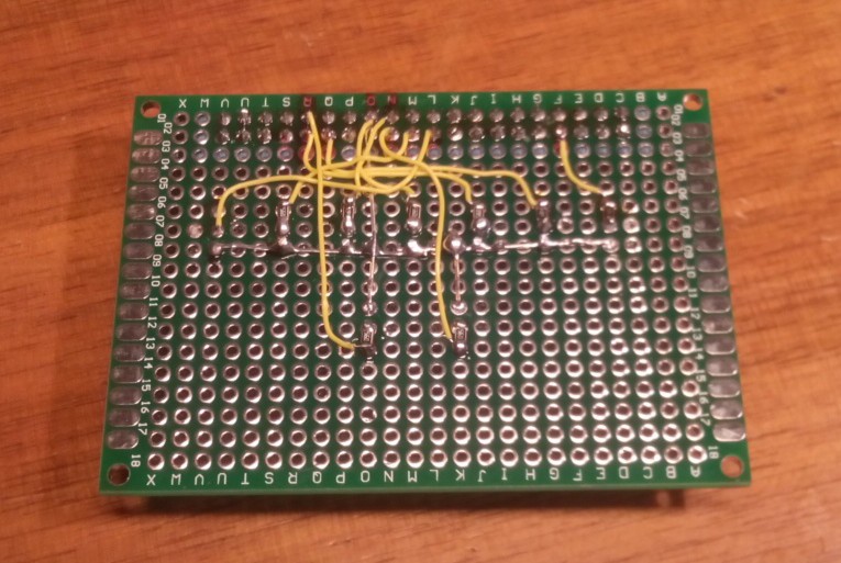
Rainbow board
Just a fancy board with 9 LEDs of different colors
Used with #micro HTTP server in C by #hammer's smashing game - Rasberry Pi
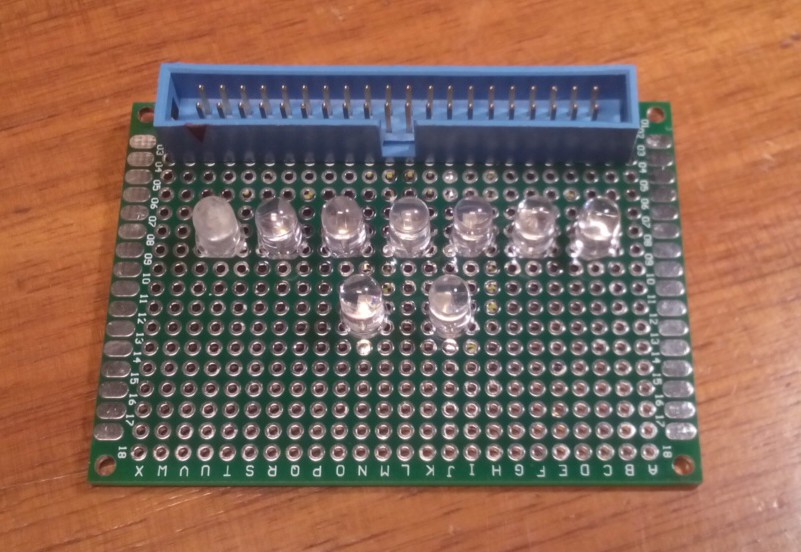
ROUGE : GPIO4
ORANGE : GPIO5
VERT_JAUNE :
GPIO6
VERT : GPIO7
VERT OCEAN :
GPIO8
BLEU : GPIO9
UV : GPIO10
BLANC : GPIO11
ROSE : GPIO12
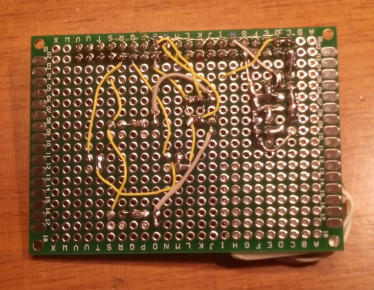
Car board
For simulations of a car's remote control
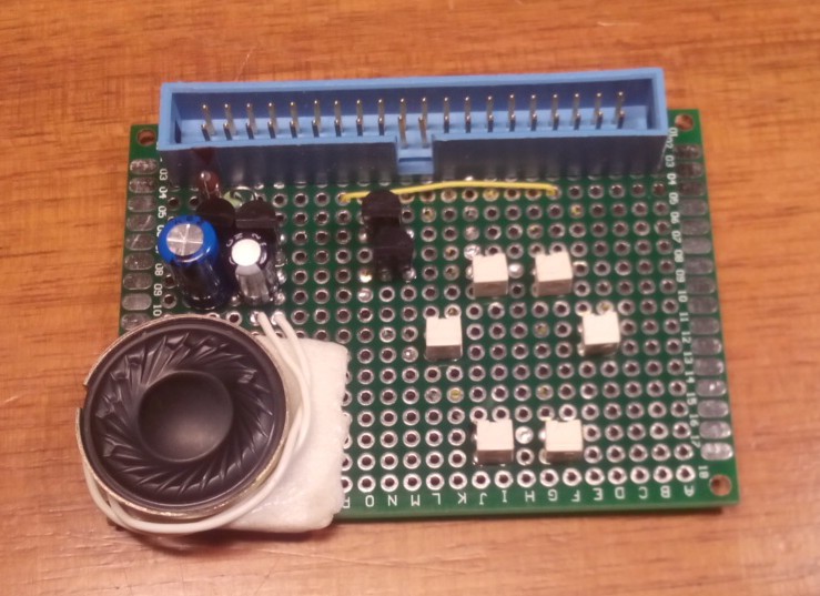
Throttle (HP) : GPIO18 (can use PWM)
Right : GPIO5
Left : GPIO6
Backwards :
GPIO7
Forward : GPIO8
Some bash code implements the roundabout pattern:
while true
do
sleep 0.5
./GPIO_on.sh 6
./GPIO_off.sh 7
sleep 0.5
./GPIO_on.sh 8
./GPIO_off.sh 6
sleep 0.5
./GPIO_on.sh 5
./GPIO_off.sh 8
sleep 0.5
./GPIO_on.sh 7
./GPIO_off.sh 5
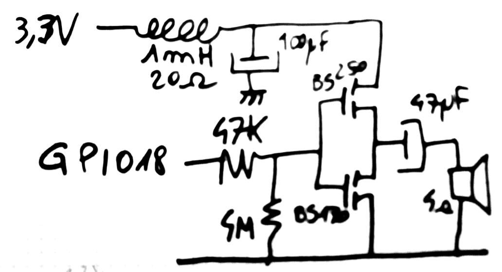
doneThe throttle output is actually connected to a dirty amplifier that drives a miniature 4 Ohms loudspeaker. No crazy magic here but I used a crude discrete CMOS amplifier (BS170 and BS250, as used in other projects) with an input resistor to reduce the bandwidth. A LC network (with L having significan R) keeps the current draw low depending on the binary signal's frequency.
Some dirty code makes it vibrate:
while  true
do
./GPIO_on.sh 18
./GPIO_off.sh 18
done
(the GPIO scripts are provided by #C GPIO library for Raspberry Pi )LED board
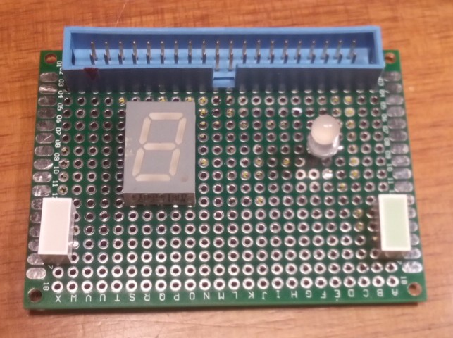
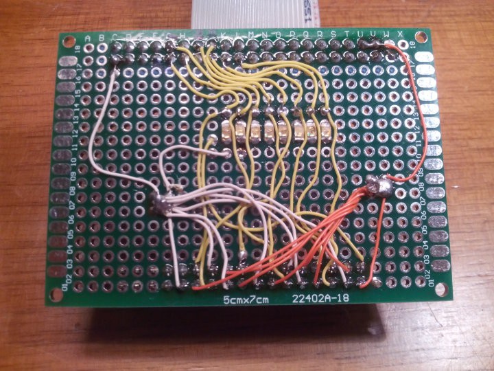
Just a few miscelaneous LED (a red block, a green block, a RGB LED (inverted polarity !) and a 7-segments (and dot) module.
RED : GPIO14
GREEN : GPIO15
RGB_R : GPIO19 (inverted!)
RGB_G : GPIO20 (inverted!)
RGB_B : GPIO21 (inverted!)
7SEG_A : GPIO4
7SEG_B : GPIO5
7SEG_C : GPIO6
7SEG_D : GPIO7
7SEG_E : GPIO8
7SEG_F : GPIO9 (assignation: to be determined)
7SEG_G : GPIO10
7SEG_H : GPIO11
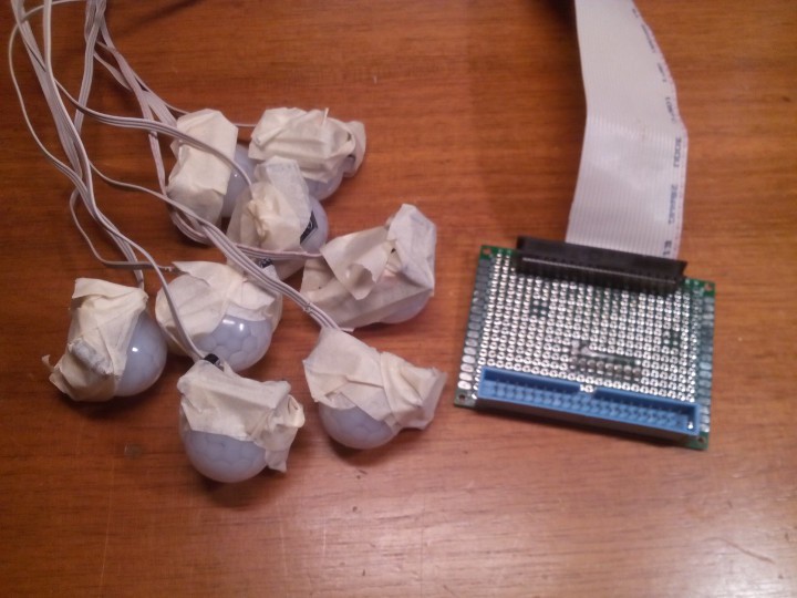
PIR board
8 inputs triggered by passive infrared motion detectors.
See http://www.azaryia.com/ for one project that uses it.
PIR1 : GPIO5
PIR2 : GPIO6
PIR3 : GPIO7
PIR4 : GPIO8
PIR5 : GPIO9
PIR6 : GPIO10
PIR7 : GPIO11
PIR8 : GPIO12
Buttons board
For dealing with simple inputs.
Used with node.js for the sampling sequencer at https://github.com/luberlu/bloopController
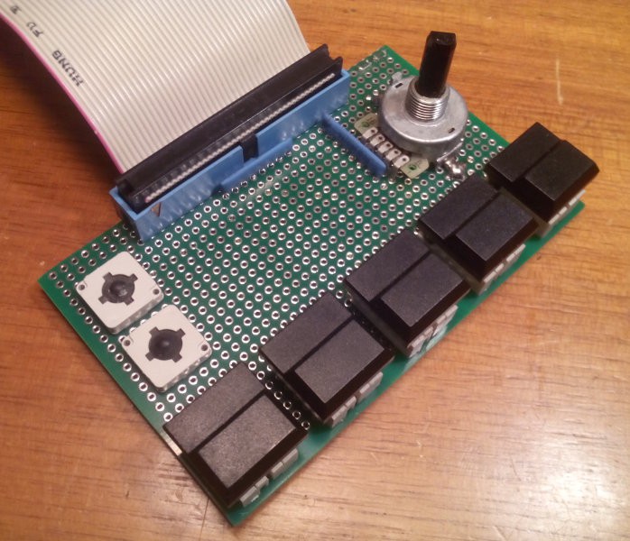
A1 : GPIO17
A2 : GPIO27
B1 : GPIO22
B2 : GPIO10
B3 : GPIO9
B4 : GPIO11
B5 : GPIO5
Hexadecimal coding wheel :
1 : GPIO6
2 : GPIO13
4 : GPIO19
8 : GPIO26
.
Discussions
Become a Hackaday.io Member
Create an account to leave a comment. Already have an account? Log In.
Can you show the different colors of the 9 LEDs on the rainbow board?
Are you sure? yes | no
hopefully, soon, when I test them :-)
However the camera might not render the colors accurately but I'll keep that in mind.
Are you sure? yes | no
Did you see the video ?
Are you sure? yes | no