 Yann Guidon / YGDES
Today's workshop started by a reminder of the basic inverter-based oscillator. I wanted to see if the kids remembered how to wire it, but I mostly wanted to use it as a customisable signal generator.
Then added a 1µ capacitor at the output, connected to nothing. The 'scope shows the square wave, that shifts toward 0V average because of the probe's impedance.
Then a diode is added to "force" the shift the square wave below 0V or above Vcc.
It's not really interesting so we add a second diode, to keep the square wave from "going backwards", then a capacitor to store the energy.
Voilà ! a charge pump !
It's one of the practical methods that can be used to generate small currents beyond the normal range of the power supply.
Then after the diodes, finally the transistors. The MOSFET is shown and the BS170 is presented and measured.
The BS170 is a sort of voltage-controlled resistor, but it has other characteristics and two "parasites" : capacitance and diode. They are explained then used to determine the pinout.
Then a basic application circuit is shown: a potentiometer generates a control voltage between 0V and 3V (connected to the gate), the MOSFET's source is connected to 0V and the drain is connected to the +3V through a white LED.
Turning the pot changes the voltage and we see that the LED starts to glow at about 2V.
There, you have an "inverting logic gate", which is actually one half of the 74HC04N we had used so far.
A RC network is added between the gate and the pot's brush signal. 1M ohms in series, then 1µF in parallel (between the gate and the source). Turning the pot is still effective but with one second of delay (in one direction).
When we replicate this circuit, we have a longer string, with more delay. With 3 stages, either 1 or 2 LEDs are glowing (don't forget the pull-up resistor).
When the pot is replaced by a wire coming from the end of the string, we end up with the circuit of the #Yet Another Electronic Lampyridae
We see what happens when only 2 stages are looped, even number=>stable (memory cell), odd number=> unstable (oscillating)
After the electronics, it's Minecraft time. The Redstone system is used and the discussion quickly drifts toward how to design a binary adder. We discuss about half-adders, full-adders, cascading the carry bit then how to perform subtraction...
From the expected outputs, we derive the equations and the logic diagram, that Adam implements in Redstone logic.
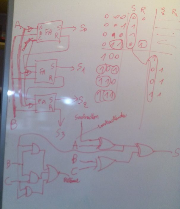
We start to think about how one Redstone element translates into actual electrical parts. For example, we favor OR gates because they are "free" in Redstone (just wire everything in parallel)
Discussions
Become a Hackaday.io Member
Create an account to leave a comment. Already have an account? Log In.