 Simon Merrett
In this log, we'll write a basic programme in Atmel Studio for the ATtiny402 which demonstrates one of its major advantages over the ATtinys and even ATMEGAs which went before: the ability to avoid the need to set fuses with a programmer.
If this doesn't strike you as wonderful, what it means is that we don't need to wait for avrdude or Arduino IDE to work out how to talk UPDI (although I'm sure it will get done soon with the new Arduino programming interface freedoms that have recently been announced) to set things like:
- Brownout detection
- Watchdog settings
- CLOCK speeds!
Yes, that's right, we no longer need to set the clock configuration before we upload code! We can even dynamically change both the clock speed AND source from within the programme! This opens up huge opportunities, such as running from the 32kHz internal oscillator down to 18uA - no need to sleep if you want the device to always be on and ready to respond to human timescale events.
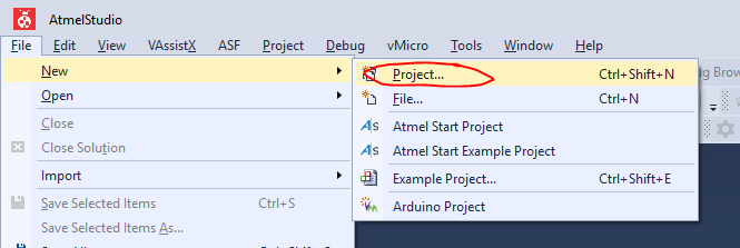
In Atmel Studio, open a new project:
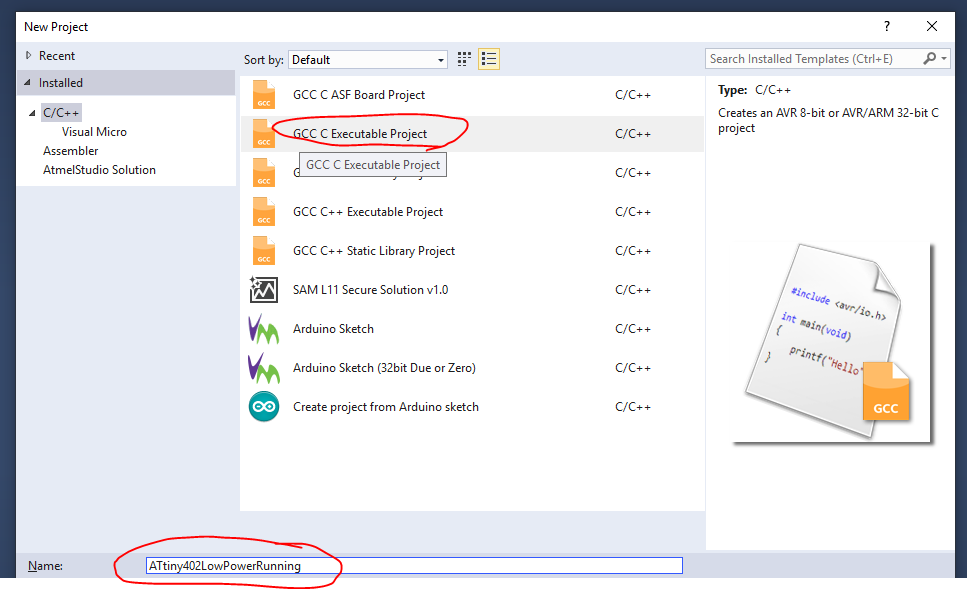
We need to give it a name (I left everything else as defaults) and then click on the option for a GCC C Executable Project and then click OK:
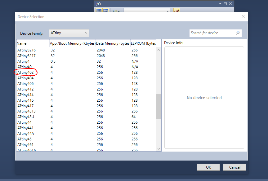
And select ATtiny402 from the parts list, before clicking OK again. It will now create and open your project.
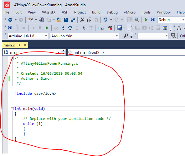
Atmel Studio will open your main.c file with the bare minimum structure in there and it will look similar to this:
However, we want some more funtional code to go in there, so how about:
/*
 * ATtiny402LowPowerRunning.c
 * These settings (F_CPU 32000UL, 0 prescaler, all GPIOs apart from LED pin set to pullup inc UPDI, force OSC20M off)
 * Result in a processor current draw of 16uA!
 * Created: 05/05/2019 20:46:56
 * Author : Simon
 */

#ifndef F_CPU
#define F_CPU 32000UL // 32 kHz clock speed / 0 prescaler divisor
#endif

#include <util/delay.h>	// needed for our delay
#include <avr/io.h>

int main (void)
{

	/* Set the Main clock to internal 32kHz oscillator*/
	_PROTECTED_WRITE(CLKCTRL.MCLKCTRLA, CLKCTRL_CLKSEL_OSCULP32K_gc);
	/* Set the Main clock prescaler divisor to 2X and disable the Main clock prescaler */
	_PROTECTED_WRITE(CLKCTRL.MCLKCTRLB, CLKCTRL_PDIV_2X_gc); // without enable
	/* ensure 20MHz isn't forced on*/
	_PROTECTED_WRITE(CLKCTRL.OSC20MCTRLA, 0x00);

	/* Configure Port A, Pin 6 as an output (remember to connect LED to PB6 and use a resistor in series to GND)*/
	PORTA.DIRSET = PIN6_bm;

	/* Set all pins except the LED pin to pullups*/
	PORTA.PIN0CTRL = PORT_PULLUPEN_bm;
	PORTA.PIN1CTRL = PORT_PULLUPEN_bm;
	PORTA.PIN2CTRL = PORT_PULLUPEN_bm;
	PORTA.PIN3CTRL = PORT_PULLUPEN_bm;
	//PORTA.PIN6CTRL = PORT_PULLUPEN_bm; // LED pin
	PORTA.PIN7CTRL = PORT_PULLUPEN_bm;


	while (1)
	{
		// PAUSE 1000 milliseconds
		_delay_ms(1000);

		// LED off
		PORTA.OUTCLR = PIN6_bm;

		// PAUSE 2000 milliseconds
		_delay_ms(2000);

		// LED on
		PORTA.OUTSET = PIN6_bm;
	}
}
Let's take the code section by section so that if you are more familiar with the Arduino IDE, we can give a nice introduction to Atmel Studio (but a VERY basic intro), to get you up and blinking from the source code.
#ifndef F_CPU
#define F_CPU 32000UL // 32 kHz clock speed / 0 prescaler divisor
#endif
This section is something we don't have to worry about with Arduinos usually, as their clocks are set outside the sketch. This tells the compiler what speed the microcontroller is going to run at - in this case I have rounded down to 32kHz exactly, although this isn't the real speed of the internal oscillator. Good enough for now but you may want to change. If we don't get this roughly right, all sorts of timer type items will go wrong, such as millis() being a different length than 1ms. Bear in mind that the clock speed is made up of both an oscillator frequency (you can also use the internal 20MHz oscillator or choose to run that same oscillator at 16MHz) and a prescaler divider, such as 2, 8, 48, 64 (not exhaustive). The oscillator speed divided by the prescaler divisor is the number you want to put in this #define. PS, it's about 3.3MHz by default from the factory, none of this 1MHz or 8MHz that we see in the ATtiny85 etc.
#include <util/delay.h>	// needed for our delay
#include <avr/io.h>
avr/io.h was already included in the project when Atmel Studio set it up for us (sorts out our GPIOs) but util/delay.h is a new one. We need it for the _delay_ms() function to work. You have probably guessed that _delay_ms() is equivalent to delay() in the Arduino IDE.
int main (void)
{
Unlike Arduino, with separate setup() and loop() sections, everything happens within main() here. However, unless code is put within the
while(1)
{
section, it will only be executed once.
In this next section, we set the main clock up to operate from the 32kHz internal oscillator without a prescaler division. The main clock isn't the only clock in the chip but it's the only one we're interested in for now, as it drives the main code.
/* Set the Main clock to internal 32kHz oscillator*/
_PROTECTED_WRITE(CLKCTRL.MCLKCTRLA, CLKCTRL_CLKSEL_OSCULP32K_gc);
/* Set the Main clock prescaler divisor to 2X and disable the Main clock prescaler */
_PROTECTED_WRITE(CLKCTRL.MCLKCTRLB, CLKCTRL_PDIV_2X_gc); // without enable
/* ensure 20MHz isn't forced on*/
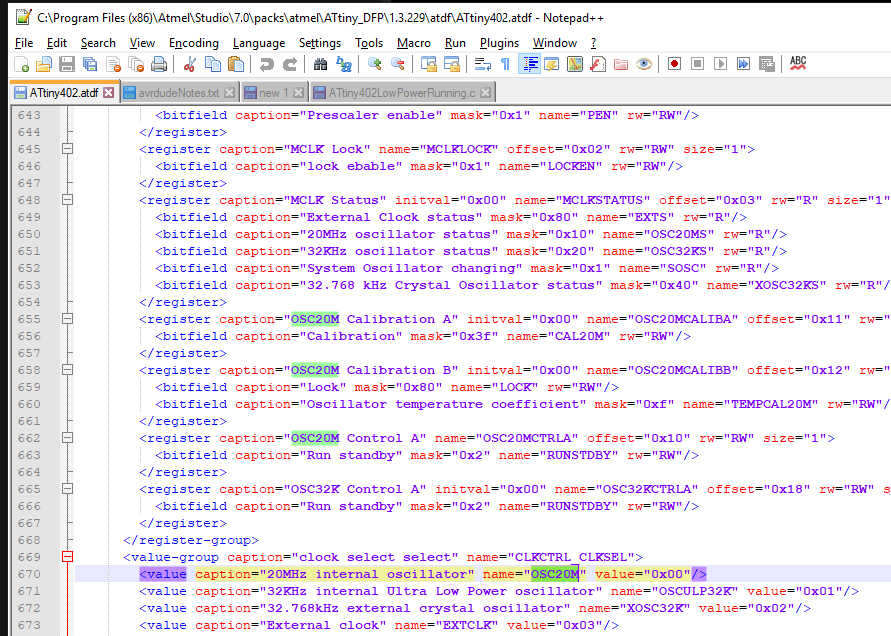
_PROTECTED_WRITE(CLKCTRL.OSC20MCTRLA, 0x00);Notice that we have to use a term _PROTECTED_WRITE. This is because critical settings registers are protected by a write key so that they aren't accidentally overwritten and stop the chip functioning. Not all registers will need this command. Within the _PROTECTED_WRITE brackets, we have the name of the register we want to write to, followed after the comma by the values we want to write to that register. The registers and values are given names within the Device Packs to make them more human-readable, rather than just being a set of hex values, although that would work if you know the values. Atmel Studio has a handy little pop-up which suggests register names when you start typing but if you get stuck, you should be able to find what you're after with a copy of the datasheet and by opening the .adtf file from the device pack in a text editor, like this:
By the way, you will see _gc at the end of some settings values. This means "group configuration". Don't worry about it for now. The other suffix you are likely to see that may make more sense, coming from the Arduino IDE, is _bm, which means "bitmask". This means we are only changing the appropriate bits in the register for that particular setting and leaving the others alone.
Now we are going to set the GPIO pins up. We want one as an output and the others as inputs with pullups.
	/* Configure Port A, Pin 6 as an output (remember to connect LED to PB6 and use a resistor in series to GND)*/
	PORTA.DIRSET = PIN6_bm;

	/* Set all pins except the LED pin to pullups*/
	PORTA.PIN0CTRL = PORT_PULLUPEN_bm;
	PORTA.PIN1CTRL = PORT_PULLUPEN_bm;
	PORTA.PIN2CTRL = PORT_PULLUPEN_bm;
	PORTA.PIN3CTRL = PORT_PULLUPEN_bm;
	//PORTA.PIN6CTRL = PORT_PULLUPEN_bm; // LED pin
	PORTA.PIN7CTRL = PORT_PULLUPEN_bm;
Port A Pins 4, 5 and 8 don't exist as GPIOs on this 8 physical pin device, as we need three for VCC, GND and UPDI. We have now finished what is the equivalent of the setup() section in Arduino.
	while (1)
	{
		// PAUSE 1000 milliseconds
		_delay_ms(1000);

		// LED off
		PORTA.OUTCLR = PIN6_bm;

		// PAUSE 2000 milliseconds
		_delay_ms(2000);

		// LED on
		PORTA.OUTSET = PIN6_bm;
	}
}
This section can be thought of as the loop() function in Arduino (note the extra curly bracket/brace to close off the whole int main (void) section). Instead of digitalWrite(), we're directly setting and clearing the registers which control the state of the pin. Very fast. Delays are made using a _delay_ms() call to the function that our #include
<util/delay.h>
brings for us.
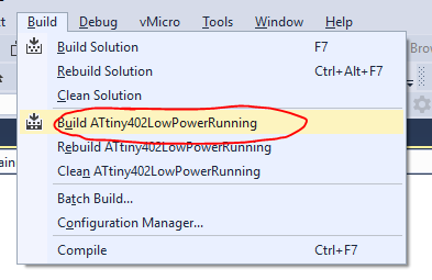
Now to compile it, we go to Build\Build ATtiny402LowPowerRunning and click it:
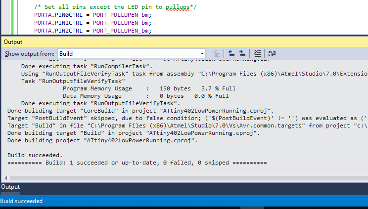
And hopefully your output shows success, something like this:
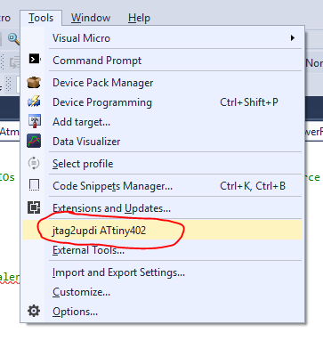
Now plug in your jtag2updi Arduino hardware programmer to the USB port and check the COM port associated with it is still the same as the External Tool command lines you saved in the previous instruction step. Make sure the Arduino is connected to the ATtiny using it's UPDI interface (VCC, GND, UPDI pin + 4.7k resistor). Then in Atmel Studio go to Tools and click on the description of your external tool:
And if you were successful you should now see that the ATtiny is blinking 1 second on, 2 seconds off. The output window of your Atmel Studio screen should show something like:
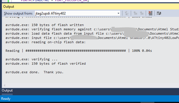
Congratulations if this is the case!
But what about that 18uA microcontroller current you promised?
Ah yes, how do we separate the microcontroller current from the LED? Take a multimeter in current measurement mode with sufficient resolution (and hopefully accuracy!) to read uA. With the ATtiny and the LED unpowered, connect the multimeter between the ground pin of the ATtiny402 and the GND rail of your breadboard or power supply, replacing the jumper wire that was previously there. Turn power to the ATtiny402's VCC pin back on and you should be able to read the promised 18uA even while the LED is on. My cheap multimeter read 16uA, so I will take that as success!
Discussions
Become a Hackaday.io Member
Create an account to leave a comment. Already have an account? Log In.
So far so good. Managed to upload a tweaked blinky to prove I was in control - well almost.
Next up - getting to grips with all those new register names and - well everything else. Here hopin'.
Are you sure? yes | no