 Alan Green
 | 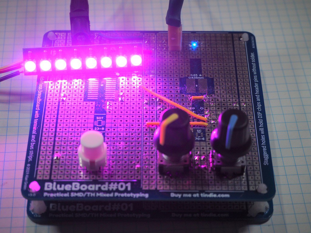 |
I began by drawing the component layout onto planning sheets.
Sadly, I lost these sheets. It was super-helpful to have them to work from, but I did change my mind, mid-construction on a few items.
Soldering Components
I have done quite a bit of prototyping with BlueBoard#01 and its predecessors. Soldering components is about as quick as soldering to a PCB. Wires are extra, but I minimized wire runs by using through hole component leads to jump between ICs, particularly around the microphone and op-amp,

- The ATTiny3217 comes in QFN package. I used a hot air gun to solder it. I was a little heavy on the solder paste, and there was one bridged pin, which I was able to touch up with the soldering iron in a few seconds.

- The SPU0410 I hand-soldered and got it third try. Fortunately, these things are cheap. Now that I've had practice, I reckon I'll get it first time, next time. The end result looks a bit messy in close up, but its fine from a distance, and anyway, the microphone is on the bottom side of the board.
Encoders
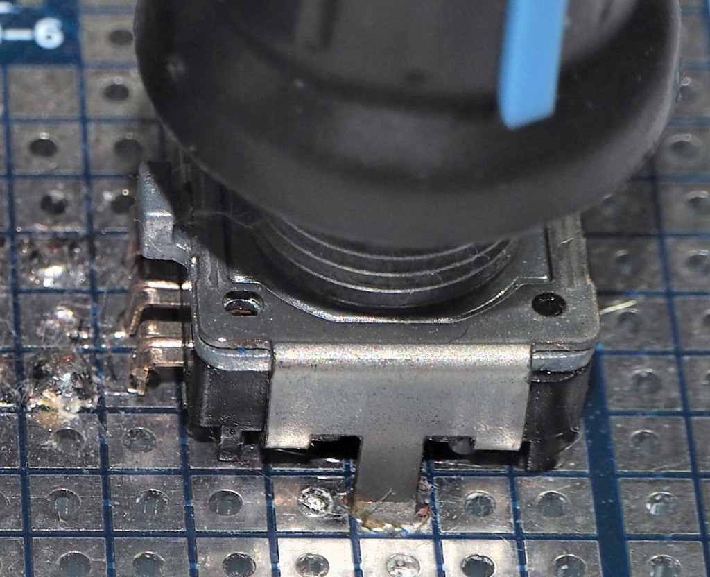
The encoders each have three leads at 0.1" centers, as well as two additional metal pegs to help secure it to the board. I was able to drill out 2mm holes in the PCB, which fit the pegs perfectly.
WS2812s
The WS2812s are connected with 3 wires - 5V, Gnd and Data, which I braided together for strength and neatness. I used a 3 pin header and plug because I happened to have them - otherwise I would have soldered the wires directly to the prototype board.
A Case
Initially, I had the idea of laser cutting a case for the switch, but I found some PCB standoffs, and it occurred to me that I had something that already had holes drilled in exactly the right location - another BlueBoard#01, so I used that. I think it looks fine.
The encoders, buttons, connectors and a couple of wires are on the top side of the board, while the rest of the components are on the bottom side, out of view. This is acceptably neat.
Discussions
Become a Hackaday.io Member
Create an account to leave a comment. Already have an account? Log In.