 burkethos
It was time to make a prototype so I designed both board types in KiCad. I wanted the LED board to be not much wider than the LED itself in an attempt to minimize the PCB visibility. The PCB will act as a viewing obstruction when used in a cube so keeping it as narrow as possible was desired.
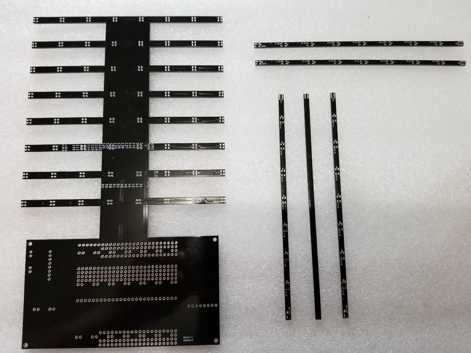
I ended up with a board .140" (~4mm) wide. This is when I hit a bit of a snag. Many of the low cost PCB fab houses have minimum dimensions on the order of .2" or .25". It took me awhile to find a fab house that could build a board as narrow as I wanted on their low cost fab lines. Eventually I found a board house and got both of my board types made in sufficient quantity to build a test cube. I procured the required components and built up a cube. The two circuit board types are shown below.
Vertical base board on the left, some LED horizontals on the right.
I mounted the vertical to some scrap wood. The controller board I picked was an FPGA board I had designed previously that incorporates an Intel MAX10 FPGA. It worked great and didn't look like anything else on the market as the pictures show.

Fully assembled cube, unlit.
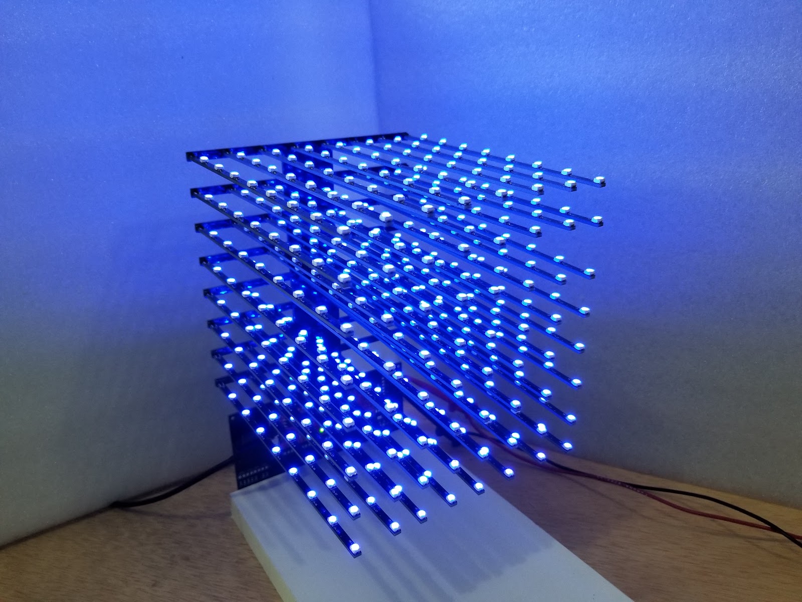
Fully assembled cube, lit blue.
But, as one of my college professors would say, this design "fell apart beautifully!"
Here is what's wrong with it: Mounting the LED boards to the vertical board so that it looks good is not easy. Yes, they just plug in and the soldering is simple. But, it is NOT easy to align them properly both across a horizontal level and then vertically from level to level. I needed one hand to hold solder, my other hand to hold the soldering iron, and a third hand to hold the LED board. The image below shows the LED board sagging a bit.
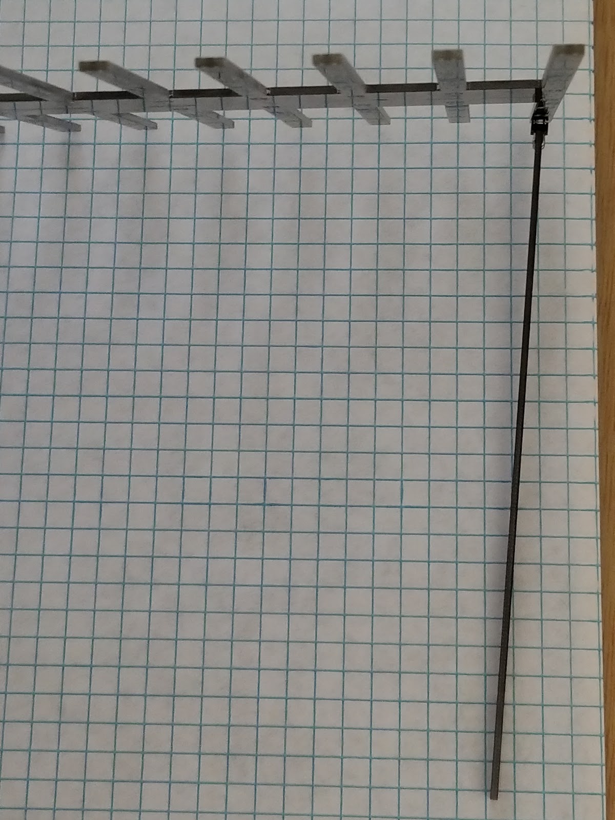
So, while the assembly part is fairly easy, making the assembly look good is decidedly not.
Heavy sigh.
I didn't want to ask the builder to jump through all kinds of hoops to try and get the LED boards properly aligned prior to soldering them onto the base board. I also didn't want to create some sort of special jig that would make the alignment process easier -- I wanted to eliminate this fiddly part of assembly completely.
Discussions
Become a Hackaday.io Member
Create an account to leave a comment. Already have an account? Log In.