 Stephen Holdaway
A couple of years ago I was part of the site-reliability team at Xero - a squad of in-flight cyber mechanics outnumbered 100 to 1 by a fleet of production servers. To cut through the daily noise of alerts, logging and system metrics, I figured a simple light on my desk to say "something's not right" would be a useful novelty. The catch? This was my second electronics projects, and I had no idea what I was doing.
Searching for "usb controllable led" in 2019 lists a bunch of devices you can outright buy, but back when I started this project in 2016 there didn't seem to be much around. At the time I referenced a single article about a "USB status cube" someone had built, but searching for that article now turned up numerous projects doing exactly the same thing as I ended up with: an AVR chip, V-USB and a bunch of programmable LEDs. I have no idea how I missed all of these at the time, but we can chock it up to blissful ignorance.
In any case, this is the story of my first PCB and how it's still a useful tool almost three years later. This isn't a build guide, but if you're building something similar you can use this as an example of what not to do.
How not to draw a schematic
In my first electronics project I'd skipped a schematic and PCB and simply used point-to-point wiring and some strip-board to hack it together. For the status light, a PCB was needed to arrange 9 surface-mount LEDs in a fixed pattern, along with the SMD WS2811 chips and microcontroller.
Now keep in mind at this point I had never laid my hands on any EDA software. I grabbed a copy of Eagle (because that's what I'd seen other people using - I recommend KiCAD now) and set to work bashing my fists on the keyboard until this monstrosity came out:

Among the overlapping, diagonal wires, lack of decoupling capacitors, lack of meaningful labels (what are those USB pins!!?) and haphazard organisation, I'd give this an F for "functional but utterly terrible". It definitely captures the "I have no idea what I'm doing, but I have a goal to achieve" spirit that comes with being a total newbie.
The crisscrossing wires were introduced during layout to make it possible to route the board single-sided, but it's a gross schematic regardless. Also note that the LEDs were desoldered/borrowed from a 12V WS2811 strip that used groups of generic RGB LEDs with separate driver ICs, so even though this design has 9 LEDs it's only three addressable columns.
For reference, here's the USB part of the schematic recreated to be actually meaningful:

PCB layout
Choosing to create a single-sided board with 50+ connections for my first PCB layout experience taught me two things:
- PCB layout is a really fun puzzle.
- People who do PCB layout professionally are the unsung heroes of this era.
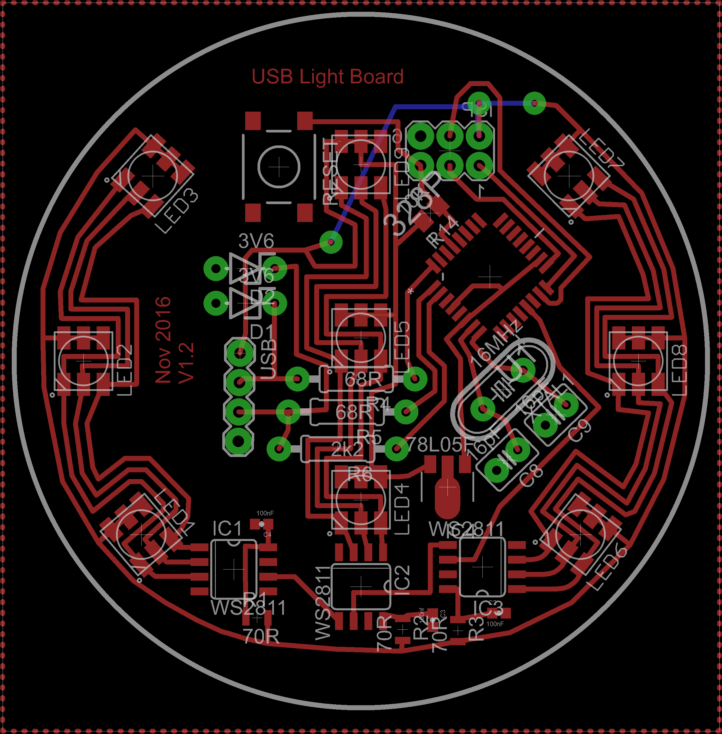
You might notice that the layout pictured is version 1.2. The first attempt (picture) ended up a complete mess of bodges as I'd missed a reset pull-up for the AVR, had multiple unconnected ground pours, and had mirrored the ISP header. The original version also had one less LED in the centre column, which gave uneven brightness so a third was added.
I won't go into detail about making the PCB at home other than saying it taught me to avoid making PCBs at home unless absolutely necessary. Sure, do it once as a learning experience, but then you'll understand why it's usually better to pay someone else to do it.

Firmware
The firmware for this original version of the project isn't particularly interesting or good, but you can download the code if you're curious. A few points of interest:
- Uses a CIE1931 luminance look-up table to achieve linear perceived brightness
- Has a breathing effect that slowly fades the brightness up and down around the selected colour.
- Transitions smoothly between colours when changed by the host.
I've had no problems using the V-USB device other than occasional packet failing to send if you spam it with control messages to change the colour.
Making an enclosure
The case for this only had a few constraints:
- It needs to sit on a desk;
- It should have space for a logo to be embossed on its face;
- It needs to be made of a material that diffuses light from the board inside.
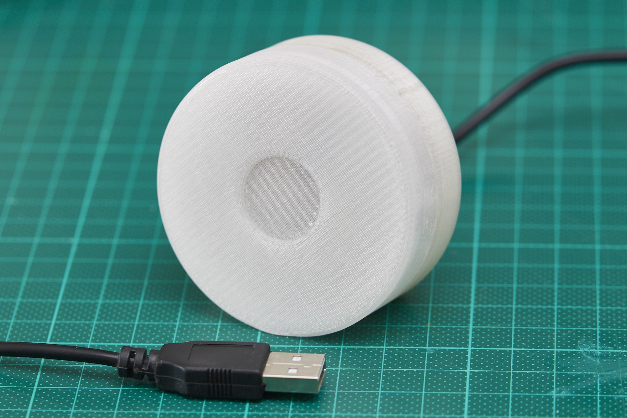
To cover these I chucked a cylinder into Fusion360, cut a 13° plane into its side to make desk-friendly base, then shelled and split the solid into a lid and base. A separate riser piece (green below) gives clearance for an IDC socket on the back of the PCB:

The interface between the base and lid has no tolerance in the design, but the layer ridges from 3D printing combined with flexible ABS plastic result in an excellent friction fit that holds firmly but can still be taken apart by hand:

The riser is glued into place as it was an afterthought, but a lip could be easily integrated into the base half to replace this.
3D printing this in semi-transparent ABS, sanding it smooth and putting the board inside gives a decent diffusion and a nice smooth finish. There aren't many decent photos of this build, so here's a frame from a video:

Fast-forward to 2019
Although this device is slightly crusty and questionable, it's actually been incredibly useful for the last two years at my job working on large compiled software projects. Not long after starting, I configured the light to glow green when a local build succeeds, and red when one fails. The colour blasts full-brightness for a few seconds to get my attention, then dims to show the last state.
When I know a build is going to take a while, this light-based notification lets me switch task completely - even something not on the computer - and get a visual indication when the build is done. It sounds like a bit of a novelty, but it's actually been a very useful tool.
For posterity, here's some photos I grabbed when I had the light back at home recently to update its firmware with some new modes.


Downloads
I won't provide the original Eagle files as they're not fit for reuse, but the rest of the project files can be downloaded below for the curious.
Discussions
Become a Hackaday.io Member
Create an account to leave a comment. Already have an account? Log In.