Sponsor Link:
UTSource.net Reviews
It is a trustworthy website for ordering electronic components with cheap price and excellent quality.
Hardware
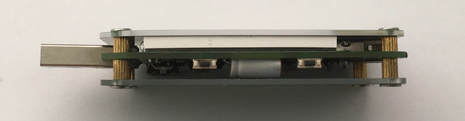
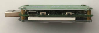
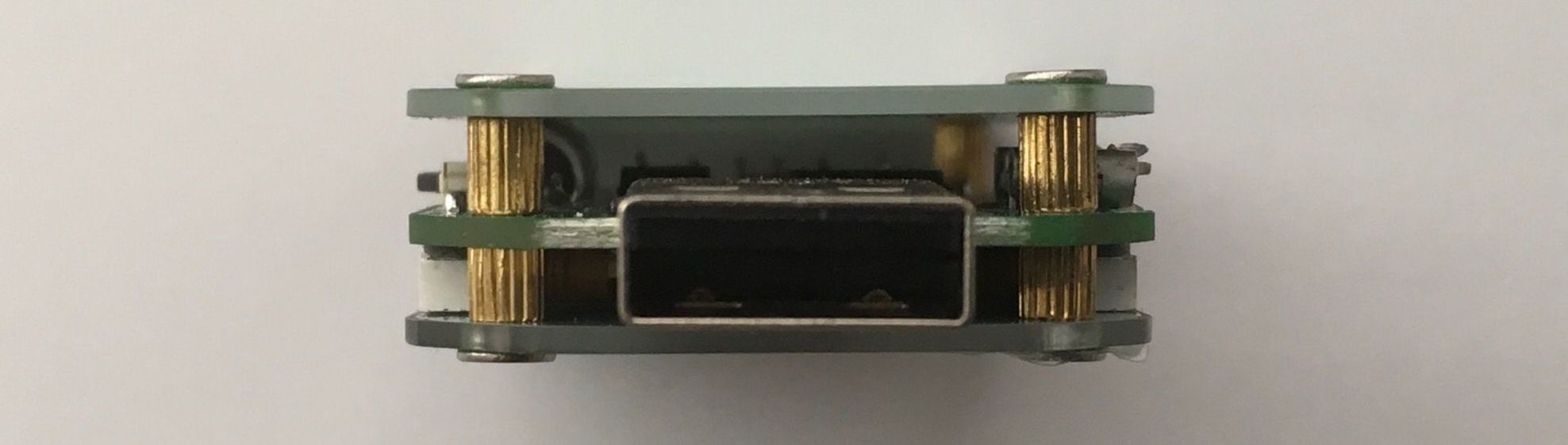
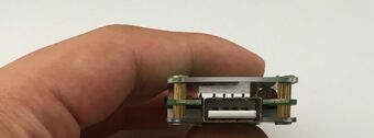
The hardware of the UM24 USB tester is not very complex and not hard to understand as it is the software which tells more about what this product can do and what it is used for. With the two USB ports for its input, the male Type A USB port and the male micro-USB port for the input voltage, and the female Type A USB port for its output to the load, this meter can be utilised for most electronic devices, with some slight exceptions, off course. There are also four buttons located on this module, as you can see on the below picture. Two on top of the module and two on the bottom of the module which are for different functions in the 7 menu pages. Then, there is the 1.44" LCD display, which is located in the centre of this meter, which we will go through in the below sections. If you have not realised, there is actually a serial port which is very unnoticeable at the top of the module, but in between the layers on the meter. You could use that port to try and change the firmware or code this module manually. Refer to the images below to see each side of this module:
How to use this module (connect the input power and load)
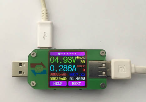
To set up the connections (input power supply and output load) for this USB meter to measure, there isn't really a lot to do so let's get into it right away. If you have a Type A Female USB connection for an input power supply, make sure you plug your supply into the Type A Male USB port located on the left side of the module, as seen in the picture below. However, if you have a Male micro-USB connection for the input power supply, you can plug that in to the Female micro-USB port located on the top of the module, as seen in the picture below as well. For the output load connection, you have to make sure your load connects to the Type A Female USB port on the right side of the module. The images below show the Female micro-USB input and the Type A Male USB input being used with the Type A Female USB port for the load:
Menu Page 1: Information Overview
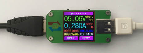
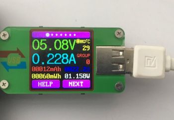
Now, we will cover the first menu page of the UM24 USB meter, which is the home page and the first thing you look at when the module is powered up. As you can see in the picture below, there are 7 white dots on the top of the display which show which menu page you are currently on, the larger white dot indicates the page you are on and the rest are the remaining pages from left to right (pages 1 - 7), this applies to all of the menu pages. On this page, you can find your input voltage, which is +5.08 volts (green text) in this case, and the current the LCD screen is drawing, which is 0.228 amps (light blue text) in this case. To the left of the input voltage, there is the ambient temperature reading (yellow text) which this meter is sensing (which is 29°C in this case), and below that temperature reading is the group reading (red text) which tells you which group you're on right now (Group 0 in this case). More about the memory groups and how it all works will be mentioned below. Then, below the text where the groups are mentioned, there is a resistance display (dark blue text), which indicates the resistance of the whole circuit (22.2Ω in this case), followed by the wattage (white text / 1.158W in this case) below. To the left of the resistance display, the mAh is displayed (red text), which is the amount of electrical charge used within an hour (12 mAh). The mWh (yellow text), the amount of electrical energy used within an hour (60 mWh), is also displayed below the mAh reading. Plus, at the bottom of all of the menu pages, are two button labels, "HELP" and "NEXT", which can be toggled with the buttons (bottom left and bottom right buttons). All of what the buttons can do will be written below:
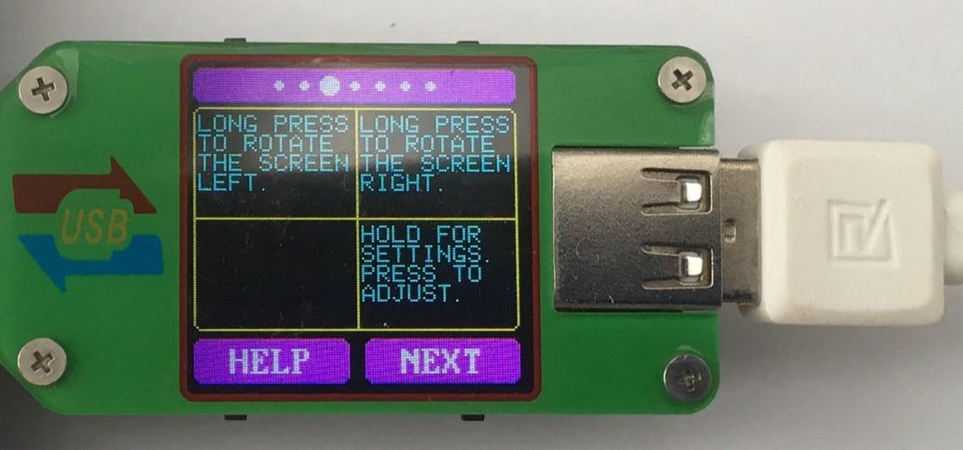
 If you click on the bottom left button which is marked as "HELP" on the display's menu page, it will show a page with 4 boxes, this page will look like the picture below, and this shows what each of the four buttons located either above or below the boxes do with that specific menu page. What each box says and the functions it performs may vary from menu pages, but this "HELP" button page will appear on every menu page though. The paragraph below will describe more on what the "HELP" page's buttons will do. However, the "NEXT" button, toggled by the bottom right button of the display will switch to the second menu page, which will be explained down below in the next section.
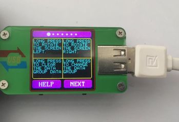 Based on the above picture of the "HELP"menu, the 4 buttons performs different functions to the display itself or a feature in that menu page. First, by long pressing the bottom left button, it changes the data group number (from Group 0 - Group 9), which you can save data from the menu page readings to the data group. Select the group you want by long pressing the bottom right button and all of the information which is shown by the numerous data readings on the menu page at that moment will be saved in that group, even when the module is off. Only the data directly before you change group or menu page will be saved in that group, meaning that you can wait for a particular set of numbers (information) to appear before saving it (changing menu page or group). You can clear all the information off that group by long pressing the bottom left button, and it will clear off the information for that specific group you are on. You must manually go to each group and clear the data, as you cannot clear every group's data at once. The pictures below shows me holding the bottom right button to go through the multiple menus (Group 1 in the image) and clearing the data using the bottom left button:
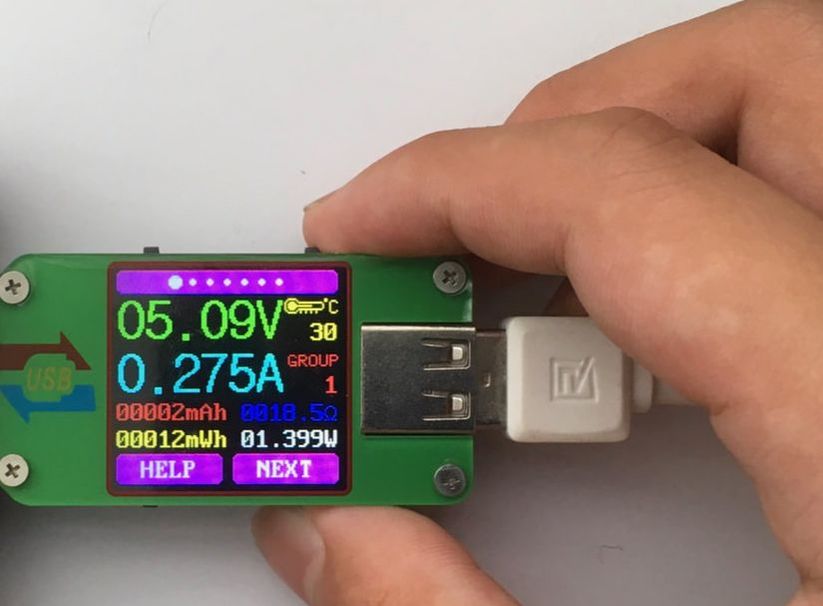
There are also two buttons which apply to every menu page, with the same functions: the top left and right buttons.
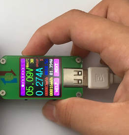
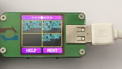
Long pressing the top right button rotates the display to the right, for vertical use of this meter when looking from the input side. Long pressing the top left button does the same thing, but rotate the meter's display to the left for vertical viewing from the output side of the meter. The top left and right buttons are available to use with every single menu page with the same features applicable to all. With all of these buttons explained, I have to inform you that you must exit the "HELP" menu, by pressing the "HELP" button again once you are on it to work the buttons or else there won't be any action. The images below show what happens to the display when I press those two top buttons: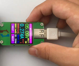
 Menu Page 2: Data Voltages and Quick Charge Modes
This menu page identifies the data voltages and quick charge modes (if it is being used) which it is using. The input voltage, current being drawn, temperature reading, data group reading, top "dot" menu display and the two buttons ("HELP" and "NEXT") are located exactly where they were in Menu Page 1. However below the current reading, there is a Type A USB pinout and the Data + (2.96 volts in this case) / Data - (0.00 volts in this case) readings (white text) to the right of it. This feature can be useful when you are charging something as you can see all of the voltages gong through the USB data lines. To the left of that data reading, you can see a section (yellow text) which identifies quick charge modes (QC2.0 and QC3.0) if you are charging a device. The image below features the data being presented, however, no mode is recognised as I am not charging anything: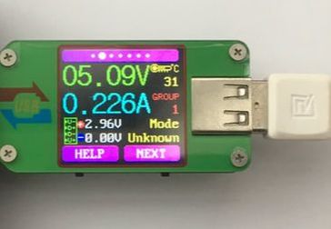 As usual, a click on the "NEXT" button will take you to the following menu page and a click on the "HELP" button will take you to the "HELP" page. However, long pressing the bottom buttons on this menu page do not do anything as it does not have a feature in this menu page. But, same as the last menu page, holding the top right and top left buttons do rotate the display either right or left when out of the "HELP" page. The image below shows you what the "HELP" page looks like as almost everything is the same as the first menu page.
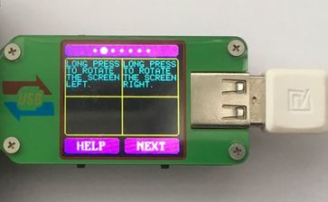
Menu Page 3: mAh (electrical energy) and mWh (electrical charge) Data
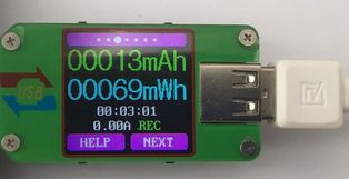
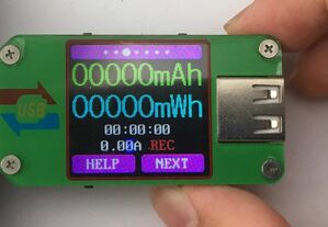
This menu page displays the mAh and mWh of your load, from your input power supply. From the top of the display, you can see the white dots indicating which page you are on, like normal. And the large green text displays the mAh (13 mAh in this case) of up to 5 digits and the mWh (69 mWh in this case), which is located below the mAh reading in the large blue text with the data going up to 5 digits as well. Below the mWh reading is a stopwatch (white text), which immediately starts counting up when a load is plugged in, even if you are on another page. If the load is plugged out, you can see that the stopwatch will stop counting and you can reset it if you plug out the UM24 USB meter and plug it back in to your power port. Below the stopwatch, you can find a current reading (white text), which you can set if you want to check what your load can take or when charging a device. More on how you can set this current reading will be down below with the buttons. To the right of that current reading says "REC", which indicates when the stopwatch is counting up. "REC" will turn green when the stopwatch is counting and charging is going on, and "REC" will turn red when the stopwatch is not counting and the load is not plugged in to the meter (the charging process is halted). Finally, at the bottom of the display, you will see the two buttons ("HELP" and "NEXT") just like all of the other menu pages. The pictures below show this menu page when my load is plugged in and out, and with the current set to 0 amps: 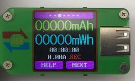
 If you click the "HELP" button like in the other menu pages, you can see what each of the buttons on this meter will do on this menu page. The top two buttons do the same thing as the last menu pages when long pressed, they will rotate the display either left or right depending on the button you press. However, if you exit the "HELP" page and long press the bottom right button of the meter, you can change the current for the output as I said above. Once you long press that button, you can see the a dark blue background go over the last digit of the current on the screen. Now, you can short press the same bottom right button to increase the digit count by one every press. You can go up to 0.30 amps and as low as 0 amps. Long press the same bottom right button to get out of changing the current and back to ordinary. This menu page is very useful when charging batteries or power banks as you can see its true capacity and how much power it needs. You can click "NEXT" like normal, to change the menu page to the next page. The images below show the "HELP" page and the current being changed (0 amps in the picture):
Menu Page 4: Input cable resistance
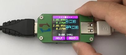
Menu Page 4 is meant to read your input USB cable resistance, if you have one. It measures your input voltage and the load current without a USB cable and then compares that reading to the one with the USB cable attached. With a simple Ohm's Law calculation, the two voltage and current readings are subtracted from each other, then, the voltage is divided by the current to get the resistance. You could end up seeing which cable is best for your application and what you would prefer. As you can see on the top of the display, the 7 dots are still visible, with the bolder dot indicating the page you are on, the fourth menu page. Below that, the green text shows your voltage and current readings which you may have now and the yellow text, below that, shows the current and voltage reading which you will soon have once that is set. More on how you can set the two separate data readings to calculate the resistance will be explained in the below paragraph with the buttons. Furthermore, to the right of those two data readings are blue images which indicates how you can connect up the load, power supply and the connection cable. Lastly, the white text below all of that is the resistance of the cable, which is the calculated final, and as all of the menu pages have, there are the two ordinary buttons: "HELP" and "NEXT". The below picture shows what the page looks like on the meter with the resistance already calculated:
 To know more about the buttons, you can click the "HELP" button (bottom left button) and all of the functions the buttons on this menu page can do will show up. The top buttons do exactly what it does on every other menu page; it rotates the display to the left or right for vertical use. Since the bottom left button has no use on this menu page, let's discover what the bottom right button can do, which is to save the first set data for this menu page in order to get the second set of data. This is used to find the resistance of your input cable. This procedure to find the resistance will be explained below:
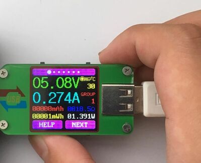
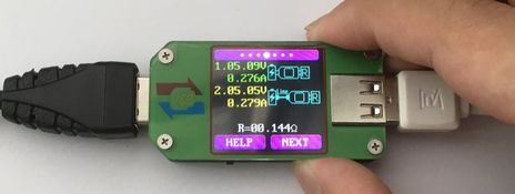
 To get the input USB cable resistance, you will need to get the voltage and current readings (5.09 volts and 0.276 amps in the picture) of your current circuit without the cable, so plug your load in and power supply into this meter and long press the bottom right button while on this menu page. Make sure you are not on the "HELP" page or it will not trigger any function. Now, your voltage and current data is set without the USB cable. The second step of this process it to take out your meter from your power supply first, and either attach a Type A Male to Type A Female USB cable or a Type A Male to Male micro-USB cable from your power supply to the meter's input port. On the same menu page, as you were on, you can see the past readings (green text) which you have set. Long press the bottom right button again to set the next data reading (5.05 volts and 0.279 amps in the picture) with the input USB cable and the yellow text will stop blinking with the two sets of data recorded. Finally, you can now see your input cable resistance which is the white text at the bottom of your display (0.144Ω in this picture):
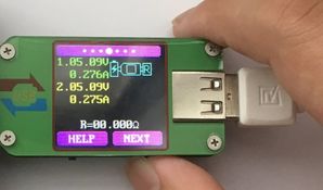
 To clear all of the existing data and cable resistance, you can just on and off your input power supply to the meter. You should now see that the resistance (white text) is set back to 0Ω and the second data set (yellow text) is also set back to 0.
Menu page 5: Input voltage graph
This menu page consists of an input voltage line graph, where you can monitor the input voltage and any changes to it over time. As for the display, and from the top, you can see the 7 dots with the larger dot indicating your menu page. And as you can see in the menu page picture below, there is a thin green line on the graph which indicates that voltage reading on that graph. The y-axis (white text) shows the 9 voltage readings in intervals of 0.10 volts going upwards and it starts on where the voltage is predicted to fall or rise. The y-axis measurements can change at any time depending on the growth or fall of your input voltage. There are also dots on the display vertically and horizontally for you to identify uneven peaks for troubleshooting or testing. Lastly, below everything on the graph, are the two menu page buttons: "HELP" and "NEXT" which you can use to trigger different things, which is described below. Based on my experience when working with electronics, this menu page is very useful when measuring/analysing power supplies and its stability and efficiency with different loads. The picture below shows this menu page with the voltage at 5.09 volts: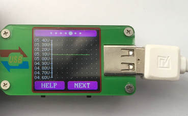 For this menu page, the bottom buttons do not do anything or change anything so there isn't really a use to them when you are on this page. However, the top buttons are only responsible to for changing the display angle, whether it is vertical or horizontal, right or left when long pressed as said before. Even if you click on the "HELP" button, the "HELP" page will not show you anything regarding the bottom buttons at all.
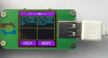
Menu Page 6: Current Graph
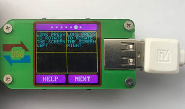
Exactly like the graph in menu page 5, this graph differs by measuring current which your load is consuming instead of its input voltage. However, the display format is very similar, with the white dots above the graph and the two buttons ("HELP" and "NEXT") below the graph. The green line which you see indicates the current your load is drawing and the y-axis represents the current, in intervals of 0.100 amps going up. The y-axis digits can change depending on the pattern of current and your predicted minimum and maximum current which it may draw. Just like the last graph, this menu page is excellent from an electronic hobbyist's perspective to analyse and collect information regarding your load and how much current it can take. The data can be collected later to troubleshoot or find solutions to problems you face with the electronics, especially when there are uneven spikes or irregular patterns within your graph's measurements. The below picture shows this current graph analysing my load (0.290 amps): 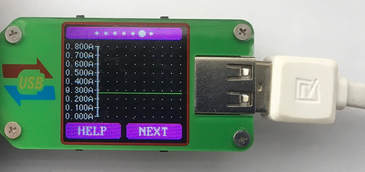 Just like Menu Page 5, the input voltage graph, the bottom buttons do not perform any operations or actions on this menu page, so pressing them will be useless. However, the top buttons also do nothing different from what you were pressing for in the last 5 menu pages. The top buttons just rotates the display left or right depending on the button you long press. You can enquire about the buttons which is usable when you are on the "HELP" page which is shown below:
Menu Page 7: Settings
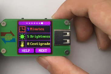
This menu page is the last menu page on this meter and is mainly used for your personal customisation of the meter itself. The top of the screen includes the dots again, with the bold dot as the page you are on. There are three boxes below that, which are all indicators of things you can change. Firstly, you can change the Auto Screen Off Time (red text) in minutes, so that the display wouldn't turn off automatically depending on the time set. Below that, you can also change the brightness of the display screen (green text) with the various brightness levels from 0 to 5 and if you didn't know, my UM24 meter is currently operating on full brightness and is perfect to see at every angle and from a short distance. The last available setting which you can change to your own preference, is the unit of measurement for the temperature (yellow text). You could switch between degrees Fahrenheit (°F) or degrees Celsius (°C). This function applies only to the first menu page, where the temperature is displayed. Finally, the two usual buttons are displayed below: "HELP" and "NEXT" which you can use with this menu page. You can see this menu page in the image below, and more about how to change the settings will also be mentioned in the paragraph below: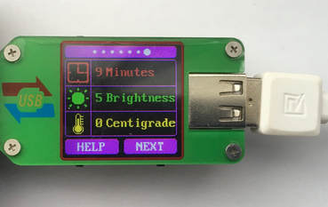 If you start by clicking the "HELP" button (bottom right button on the menu page), that will bring you to the "HELP" page, where you can see that the top buttons only are responsible for rotating the display to the right of left. But, the bottom right button is responsible for changing the settings and that will be all explained in the below paragraph. Also, the "NEXT" button just goes to the following menu page, which goes back to Menu Page 1 since Menu Page 7 is the last one. This image is the "HELP" page on this menu page:
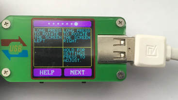 To change the three available settings on this menu page, first, start by holding down the bottom right button until a blue background comes on the one digit of the Auto Off Time setting (red text). Once you see that, you can keep on clicking that same bottom right button to change the amount and in this case, for the minutes, you can change it between 0 - 9 minutes. Then, if you need to move on to the next setting below, the brightness, just hold the same bottom right button and the blue background will move on to the brightness setting box, which you can click the bottom right button to change the brightness from 0 - 5. Lastly, the last available setting which you can change is the temperature setting, which you can alternate between degrees Fahrenheit (°F) and degrees Celsius (°C). Again, long press the bottom right button from the brightness setting to switch that blue text background to the digit (0 or 1) on that temperature setting box and with a click on that same bottom right button, you can change it right away. Long press the bottom right button again once you are on the temperature setting to return back to the ordinary menu page. That is everything done with the settings and the picture below shows the Auto Off time setting which I am changing to 9 minutes:
Conclusion
After going through every single aspect, feature and detail of this product, I would highly recommend it to anyone who is into the electronics field. Compared to other USB testers and USB "doctors", it has an advantage over others because of its display screen, menu pages and the buttons on this module. The analysis, measuring and memory functions on this UM24 USB Meter play a big part into why I really enjoy working with this tool, whether it is in the lab or out testing electronics in the field. The biggest aspect which definitely caught my eye was the RGB (Red Green Blue) colour display, with a size of 1.44". This screen displays every bit of information well and it is considerably sharp. All in all, this meter is a definite electronic go-to for me and is recommended to everybody!
Amazing opportunities
Also, be sure to check out PCBWay, a leading manufacturer and distributor in PCB design and manufacturing. They have amazing prices and excellent quality in their services, so don't miss out on them! Plus, PCBWay has an amazing website, online Gerber viewer function and a gift shop so make sure to check out their links below:
PCBWay Free Online Gerber Viewer Function: https://www.pcbway.com/project/OnlineGerberViewer.html
PCBWay Gift Shop: https://www.pcbway.com/projects/gifts.html
Make sure you check out the review for this meter by clicking here.
Enjoy! Contact us for any inquiries!