 paulusjacobus
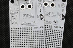
The objective is to have a replacement flexible PCB limit switches/x axis connection drop in for K40 lasers (cheap eBay lasers that can be bought for under $350-450). These come in various versions with some equipped with mechanical switches. Due to the large hysteresis of the on/off engagement distance (4-6mm) you loose some workable space. However the slotted opto couplers have much shorter hysteresis (2mm) and are more accurate in terms of positioning.
So how did I go with designing such a flexi PCB (the contest was my inspiration)?
First of all I had to source the eagle libraries for the 12 pin FPC connector and the 4 pin JST XH connector for the X axis motor. Here is Google my best friend and I sourced two eagle libraries see the attachments.
The first idea was to incorporate the entire flex FPC cable as a flexi PCB but ran into trouble with Eagle (space and library). I'm pretty sure that someone smarter can do it but for now I decided to do just the X and Y limit switches (slotted opto couplers) and the X axis motor feed. You still need to add a long 12 position FPC cable (RS online, element14, aliexpress etc).
The schematic is very simple and straight forward. No existing schematic exists so I came up with the most likely design that the K40 designers would have used.
Holes need to be adjusted and aligned so that is something to be considered. I will update the design once I have done this.
Unsure if such a simple but incredible useful for K40 owners design can win a flexi PCB price...!
 Abduulah Omran
 Carl Bugeja