borosLab
-
1st version Arch & component choice
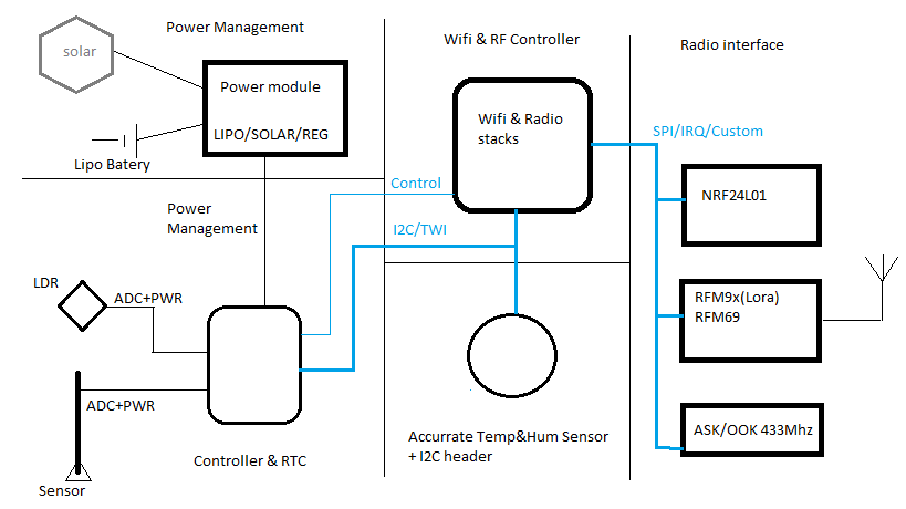
05/21/2019 at 17:15 • 0 commentsAs first approach the architecture is the following:
![]()
Wifi & Controller.
Cheap Wifi modules are available but most popular are ESP8266, ESP32 due to huge user base and friendly development environments such Arduino IDE. Other alternatives such RTL8710 could be considered as experimental for makers, Also for battery powered application ESP show better results (https://blog.voneicken.com/2018/lp-wifi-other/)
ESP32 would be the best solution as it:- Super fast dual core.
- Has Wifi & BT.
- Has lots of IO pins with several ADC entries.
- Has a ULP processor that can use TWI and analog inputs & RTC to wake the main processors. UPL could act as a simple controller.
But for the project it present some issues:
- Too much features for this simple project.
- Bigger footprint.
- More expensive then ESP8266+controller.
- ADC accuracy is on dispute for this chip.
- UPL require asm programing which is not friendly.
- Higher power requirements in run mode: Recommended regulated power to 500mA for peaks.
My decision was to experiment with STM32 family for the controllers. In particular with the cheap STMF030F4 that can be adquired for less than $0.5 in small quantities.Radio interface:
Standalone radio modules with SPI interface.
LORA
For Lora Hope RFM9x are very popular and are widely available for $5-$6. This modules have improved alternatives with shielding and FCC certification such HPD13 and NiceRF Lora1276-C1. They share same pinout and are interchangeable. Reference https://www.rocketscream.com/blog/2017/08/21/the-sx1276-modules-shootout-hoperfs-rfm95w-vs-nicerfs-lora1276-c1-vs-hpdteks-hpd13/
Key parameters:
- 1.9 -> 3.6 V input voltage typical 3.3V
- SPI interface up to 10Mhz wih additional 3 IRQ lines (high level).
- About 120mA peak current during Tx.
- Typical freqs are 868Mhz(Europe) , 915Mhz (USA) , 433Mhz (China).
NRF24
Improved SMD modules with cloned nrf24L01+ with chipset Si24R1. This claim to be compatible to and have with enhanced output power. AI-thinker's NF-03 module https://datasheet.lcsc.com/szlcsc/Ai-Thinker-NF-03_C115101.pdf is available for $2-$1.
Key parameters:
- 1.9 -> 3.6V input voltage. typ 3.3V
- SPI interface with 1 IRQ(optional) low level up to 10Mhz.
- About 15-20mA Tx peak output.
- This module uses 2.4GHz ISM band.
RFM69
FSK modem RFM69 are also used in DYI project as they. The radio footprint is compatible with RFM9x only in the HCW versions. They are widely available for around $3-$4.
Key parameters:
- 1.8 V -> 3.6V input voltage typ 3.3C
- SPI interface with 1IRQ line high level.
- About 130mA peak current during Tx.
- Special feature such hardware CRC & AES-128 encryption.
- Frequencies: 868 , 915 and 433 Mhz.
Note: As i do not use this modules software supporting this module, but a library for implementing it is available: https://github.com/LowPowerLab/RFM69
OOK/ASK 433Mhz:
There are a several transmitters of transmitters that require only 3 pin connection VCC-DATA-GND. With standard 0.1 inch headers. Some examples are shown here: https://goughlui.com/2016/05/01/shootout-four-433-92mhz-askook-transmitter-modules-compared/
They are really cheap. Some stores offer 5 pieces from less than dollar.
Power Management:
Must provide the device with stable and regulated output that support with ESP and controller.
Temperature Sensor:
-
Testing the moisture sensor
05/14/2019 at 07:11 • 0 commentsAfter testing the sensor just a brief summary.
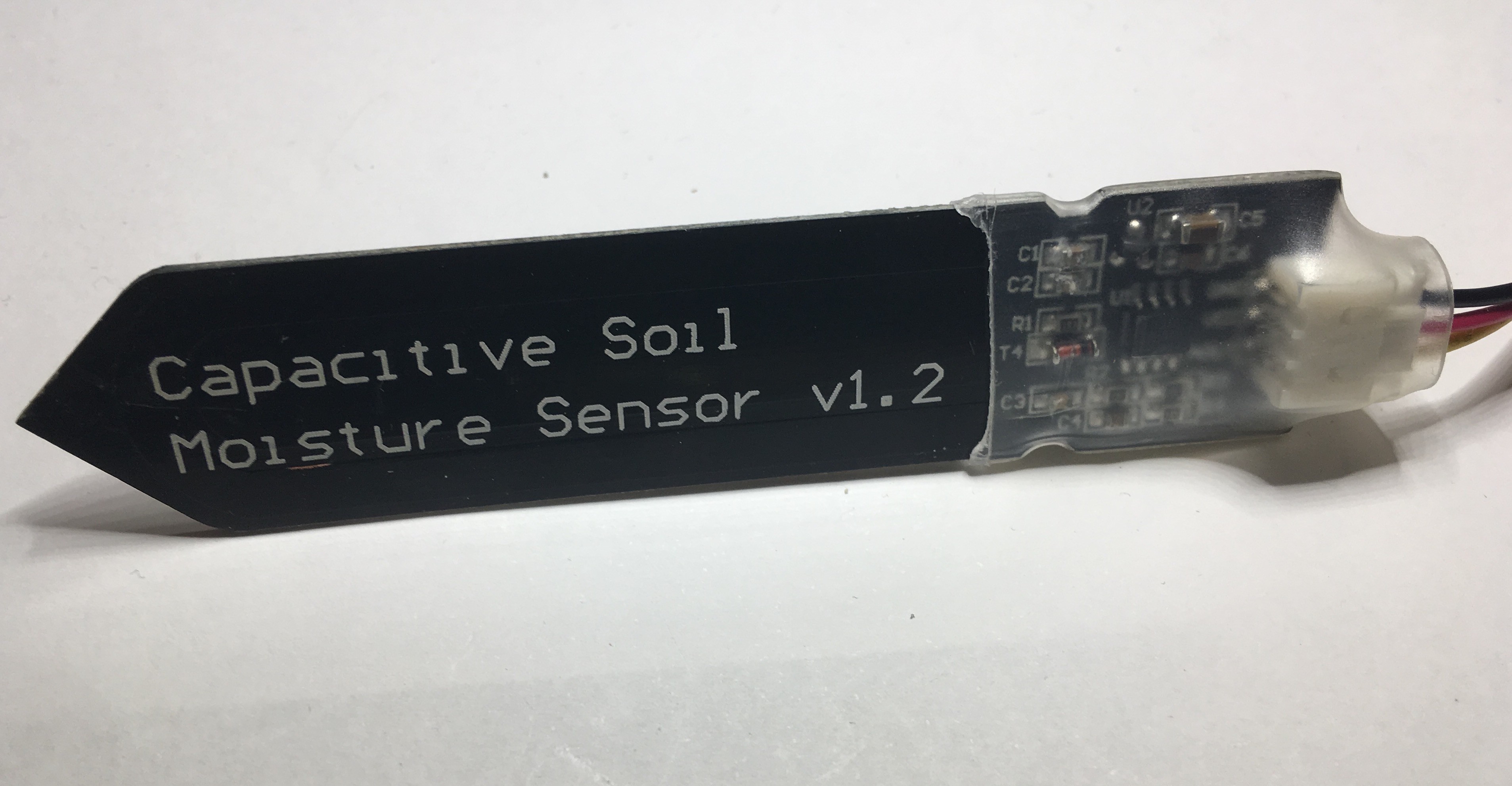
The sensor used is a cheap one purchased in china. Has no brand and is labeled as v 1.2. After a brief inspection the sensor seems to be similar to DFRobot's. A capacitive sensor based on a 555 oscilator to measure the capacitance of the pcb tracks on the sensor area:
![]()
Output is measured and confirmed that output is pulled down with a 1M resistor decoupled with a 1uF cap.
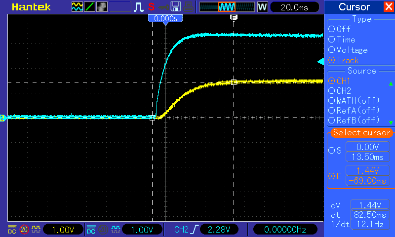
0. Sensor range: Range is confirmed with documentation. Dry (air dry): 2.8V / Water (humidity saturation) with tap water: 1,44V. This leave a sensitive range of 1.4V. this range is big enough for a 10-bit ADC.
1. Startup time: When the sensor is powered from a bench power supply at 3.3V the output response require some time to output stable voltage for measurement.
When sensor is submerged in water the response is the following (blue->VCC , yellow-> sensor output):
![]()
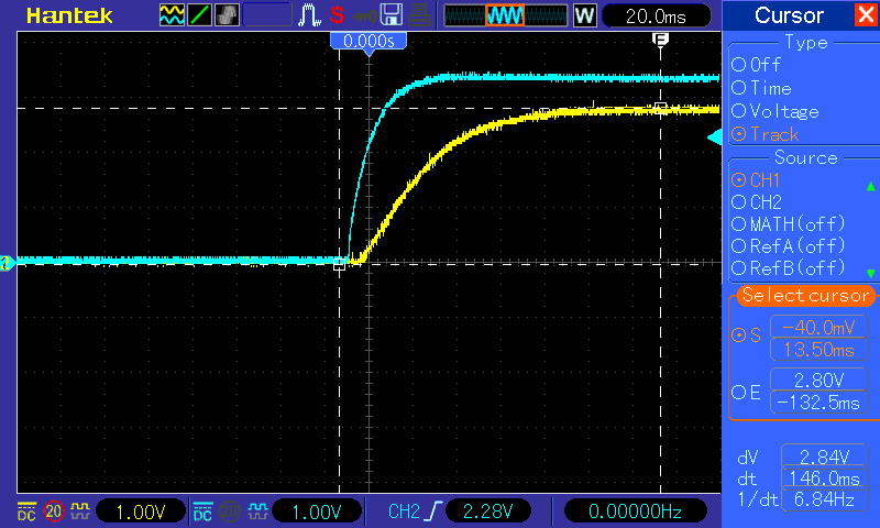
On dry air the sensor response is similar but it require more more time as the output voltage is higher:
![]()
This measurements provide a estimation for the response time of the sensor: 150ms
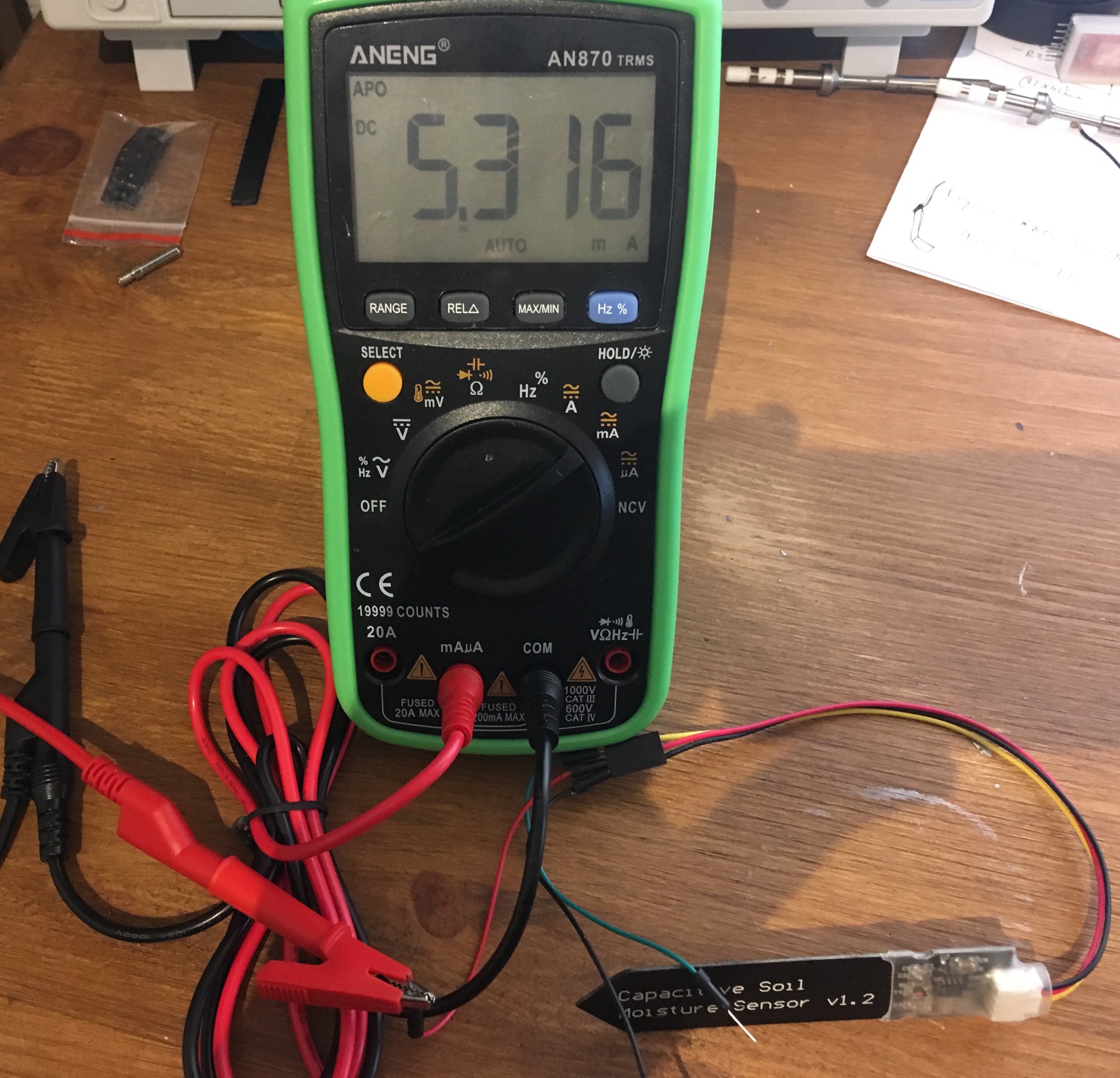
2. Current drawn: At 3.3V with the sensor floating output the current used by the sensor when power is in line with the specs: 5.3mA.
![]()
3&4: Testing output stability and measure response:
To test sensor output I carried out simple experiment with a small pot & compost. I logged the sensor output using a Wemos D1 and small sketch to send over TCP every 2 minutes the reading of the sensor. On the server side I used my local node-RED al the readings.
10 samples of the sensor are measured, the value transmitted is the average of the measure and also the standard deviation of the 10 samples are computed.#include <Arduino.h> #include <ESP8266WiFi.h> #include <math.h> const char *ssid="xxxxx"; const char *pwd="xxxxx"; // Report every //#define REPORT 10*1000 #define REPORT 2*60*1000 void connectWiFi() { Serial.println(); Serial.println(); Serial.print("Connecting to "); Serial.println(ssid); /* Explicitly set the ESP8266 to be a WiFi-client, otherwise, it by default, would try to act as both a client and an access-point and could cause network-issues with your other WiFi-devices on your WiFi-network. */ WiFi.mode(WIFI_STA); WiFi.begin(ssid, pwd); while (WiFi.status() != WL_CONNECTED) { delay(500); Serial.print("."); } Serial.println(""); Serial.println("WiFi connected"); Serial.println("IP address: "); Serial.println(WiFi.localIP()); digitalWrite(2,1); // Led on initialization } uint32_t order; void setup() { pinMode(2,OUTPUT); digitalWrite(2,0); // Led on initialization Serial.begin(115200); // We start by connecting to a WiFi network connectWiFi(); order=0; } ADC_MODE(ADC_TOUT) void measure(uint16_t *m,float *std) { const int n=10; uint16_t v[n]; int i,u=0; double std_dev=0.0; // compute avg for(i=0;i<n;i++) { v[i]=analogRead(A0); u+=v[i]; delay(1); } u=u / n; // average // compute std dev for(i=0;i<n;i++) { std_dev += (v[i]-u) * (v[i]-u); } std_dev = sqrt(std_dev/n); // std_dev *m=u; *std=std_dev; Serial.printf("T:%lu, mean:%d, std dev:%f\n",millis(),u,*std); } uint32_t last_report=0; void loop() { uint16_t m; float std_dev; if(WiFi.status() != WL_CONNECTED) connectWiFi(); if((millis()-last_report) > REPORT) { digitalWrite(2,0); // Led on initialization measure(&m,&std_dev); WiFiClient client; if(client.connect(IPAddress(192,168,4,1),8266)) { Serial.print("Sending..."); client.printf("%d,%d,%f",order,m,std_dev); order++; client.flush(); delay(500); client.stop(); Serial.println("sent!"); } last_report= millis(); digitalWrite(2,1); // Led on initialization } }
1st I dry the compost in the sun to simulate a dry soil.2nd I insert the sensor in this dry soil for a while and check the consistency of data.
3rd I water the soil and let the soil dry to check the evolution of the reading until the soil is dry again.
The data is analyzed with simple R commands:
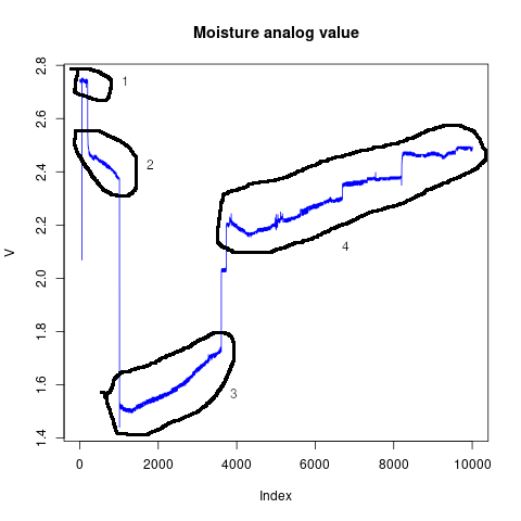
# Load data
no_cover=read.csv("doc/moisture_data_nocover.csv")

# Convert ADC Reading to volts
V <- data$value * ( 3.3 /1024)

png("doc/moisture_nocover.png")
plot(V,col="blue",type="l")
title("Moisture analog value")
dev.off()
png("doc/moisture_stdev_nocover.png")
plot(V,data$stddev,col="red")
title(paste("Mositure stddev mean:",mean(data$stddev)))

dev.off()
Results are the following:
![]()
Notes:
- Sensor in Dry Air: Stable near 2.8V.
- Sensor in Dry Soil: After insertion the sensor reacts fast to a 2.5 - 2.4: to dry soil.
- Soil watered and let dry. Response to watering is fast: The value respond slow to drying with a linear trend.
- While drying the sensor show a no linear response near 1.7V jumped to 2.0V and then stabilized around 2.1V. Then the drying continue in more or linear but with a milder slope.
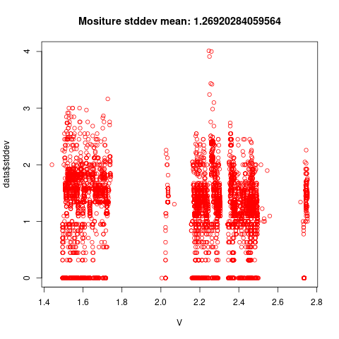
![]()
The sensor shows stable readings maximum stddev is 4 units (of 10-bit resolution). Typical Std dev is low to 1 unit. This deviation is probably due to ESP2866 ADC reported by various user as volatile especially when WIFI is connected.
Conclusion
- Sensor performance is sufficient for the project:
- Stable output with little variation on output.
- The sensor response fast to watering events.
- The sensor do not show a pure linear behavior but is suitable for a linear approximation with upper and bottom limits and 3 or 5 linear ranges.
- Sensor consumes 5mA and has a slow response time aground 150ms to have stable reading. Power need to be gated for low power applications with big ADC window.
Next Steps on the sensor:
Repeat the test using a protected sensor. (TODO)
-
The Sensor
05/13/2019 at 16:18 • 0 commentsSelecting the sensor & testing the sensor:
After some research I decided to go with cheap Capacitive sensors. They are sold for $2 in typical makers maketpaces such ebay or aliexpress. possibly they are not great but for the purpose of the projects accuracy is not a big deal. I expect to be able to control a simple scale of moisture such dry,almost dry, good, wet and very wet. This levels needs to be calibrated in the configuration. But for now this will not be relevant.
Al details of this kind of sensors can be found here: https://wiki.dfrobot.com/Capacitive_Soil_Moisture_Sensor_SKU_SEN0193Key parameters for this project:
- Works with 3.3V as input. The sensor has its own voltage regulator to 3V.
- Consumes 5mA in operation. This is not Low power friendly. [power need to be gated]
- Analog output is pulled down with a 1M resistor and will be less 3V. The output diode will drop the output voltage 2.8-2.4V.
- High voltages means dry, low voltages means wet. According to the documentation arround 1V range can be managed.
To test:
- Verify power consumption stand alone.
- Test response time on power up.
- Test variablity of consecutive readings.
- Dynamic test: Record one run of the sensor from wet soil to dry soil. To check linearity.