 Giulio Pons
As usual, the problem isn't a new problem, and this isn't a new solution. But I will describe it to help someone doing the same.
With this project I've made a wifi infra-red remote control for my Daikin air conditioner.
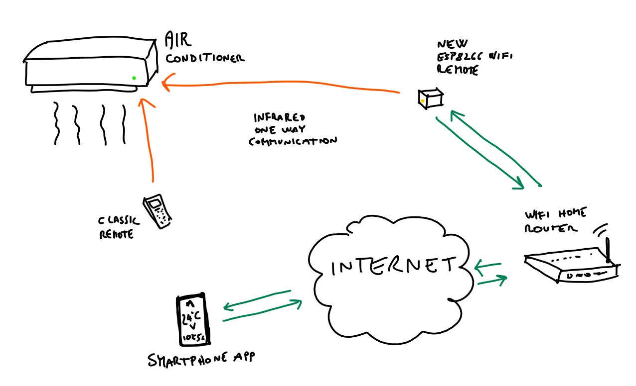
In these schema you can see all parts involved.
Some more details:
- normal air conditioner is controlled by an infra-red remote controller (top left in the pic: "classic remote");
- an ESP8266 project, closed up in a small box (top right in pic: "new ESP8266 wifi remote"), can talk with your air conditioner with infra-red communication;
- in the ESP8266 project I've added a temperature and humidity sensor to monitor in-home conditions;
- trough the router the ESP8266 box can connect to internet and talk to an app in my smartphone;
- both the classic remote control and the new ESP8266 controller talk one-way to air conditioner, it receives commands and makes a beep, but it doesn't talk back to the remote control;
- knowing the IP address of the router, I can talk to your ESP8266 through internet;
- to talk from the Internet to a device in your home wifi network, I've needed to assign a port to my ESP8266 in my router configuration;
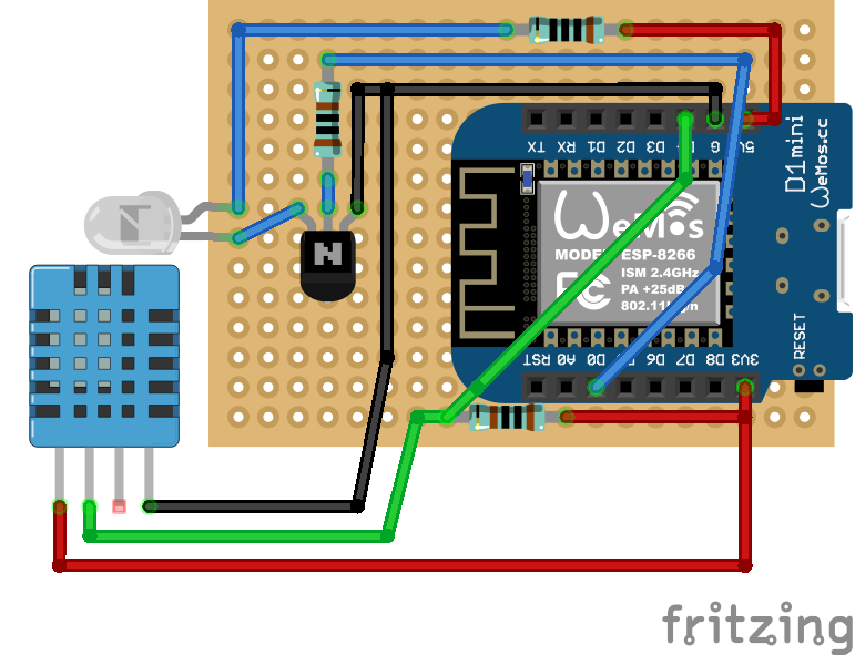
Construction of the ESP8266 based WIFI controller
Here is the schema for the wifi controller. I've used a Wemos D1 mini because it's small and cheap, it's based on the popular ESP8266 chip and works perfectly with Arduino IDE.
So in this text the terms ESP8266 and Wemos are interchangeable.
As usual, first I've built it on a breadboard and when everything works, I began to solder.
Pin D4 is used to read temperature and humidity from DHT11 sensor.
Pin D0 is used to send signals to the infra-red led. It's connected to the base of the NPN BC547 transistor which is used as a current amplifier. The infra-red led will talk to air conditioner with impulses so we can use it to drive more current that the WeMos pin can source. A couple of resistors are used to reduce the current to the base of the transistor (1 Kohm) and to limit the current in the led (100 ohm) *.
* = a couple of lines about the values of this two resistors should be written (need help).
(The DHT11 sensor in my project is different from the one in the schema, the one I've used is a module which already contains a 10k pullup resistor, so the resistor of 1kohm between 3.3V and signal pin of DHT11 could be removed) **
** = I should better understand this point (need help)
The network rules and Internet calls
In the Setup( ) section of the code in the Wemos a wifi client that connects to the local home network is started, and the router will give a local IP address to the Wemos. In Setup( ) also a web server is started, which can answer to http calls in your local network.
Here is a drawing to understand how IPs work. Every router creates a private network.
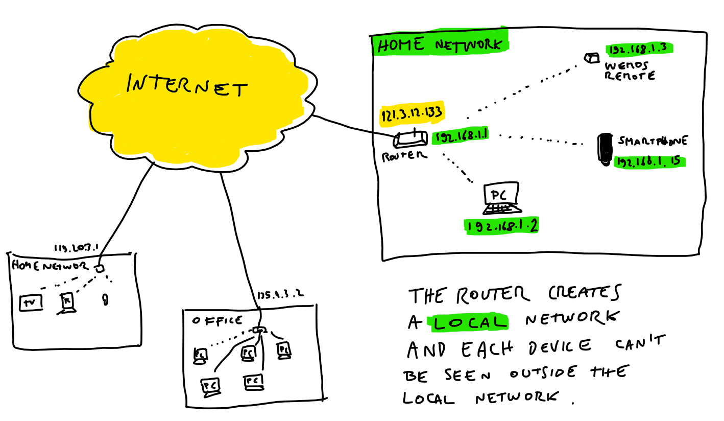
All the local addresses have the same structure and changes only for the last number: 192.168.1.x (depending on your router you could have a different structure, such as 10.0.0.x, etc.).
The code in the Wemos defines that the Wemos can answer to these 3 commands:
  server.on("/onoff", switchAcOnOff);
  server.on("/sensor", sensorData);
  server.on("/temp", temperatureSet);
So, if the IP of the Wemos is 192.168.1.3, you can open a browser and put in the URL the address 192.168.1.3/onoff to call the function "switchAcOnOff" in your Wemos.
In this way I can send command to the ESP8266, through http url calls.
But outside the local network the ESP8266, as all the other devices, are not visibile.
Outside all the local network is hided by the router, which can be reached with its public IP address, 121.3.12.133 in the drawing.
To send a command from outside my home network to the ESP8266, I need to configure the router, which is the entry-point of my local network. Depending on the router you have, you can probably access the config panel of the router by typing it's address in the URL of the browser. The IP address of the router is the first, in my case it is 192.168.0.1.
In config panel I have to forward the traffic coming from internet to the router to my ESP8266 device. To config the router I've used "port forwarding".
Everytime a call is made it happens through a "port". For example, web site calls on Internet use port 80.
To separate the traffic of our project from normal web traffic through your router, is better move from port 80, because it's regulated by router and it's firewall. So I've decide to use port 8080. To use a different port such as 8080, it's enough to append ":8080" to the ip address in every http call. So the call to turn on off the AC will be: 192.168.1.3:8080/onoff.
The "port forwarding" configuration let me forward traffic coming from Internet to my router on port 8080 to port 8080 of my ESP8266 device, specified by it's local IP address.

Finally there is another configuration, which is useful. Since IP address are assigned by the router to your device everytime it is switched on, if I unplug the ESP8266 and reconnect it to the power, it could receive a different IP from the router, so the port forwarding configuration will not be used. For this reason I've configured the router to give always the same IP to my ESP8266 device, this configuration in my router panel is named "Static lease", so I specify that the device with Mac Address (which is a string like this: a0:10:a6:16:b8:15) must always receive the IP 192.168.1.3 (it's a static IP for my local network).
Inside the loop( ) I keep checking the connection and every 3 minutes I make a call to google, just to tell the router that the device is online and working, because I've noticed that my router if nothing happens for a while it will consider my ESP8266 disconnected and no messages are forwarded through port 8080.
Infrared communication
To talk to a device that uses infra-red communication I've first tried to decode the messages from the remote control, to accomplish this mission you have first to build an infra-red receiver and use it to read the commands sent by the remote control.
The commands are simply read as a sequence of bytes, and you can store them and transmit them with an infra-red led.
But, while doing this, I've discovered that Daikin hides some informations in the commands because the same message is sent as different sequences of bytes each time, so I've searched the Internet and found this library for Arduino to talk to Daikin AC. I've tried it and it works, so I've used this lib.
The bytes that compose the commands are transmitted as a sequence of impulse, this is why a simple led can transmit informations with bytes, they are binary encoded.
DHT11 sensor
I've added a temperature and humidity sensor, first to read the temperature of the room, which is necessary if you have to decide remotely to turn on the AC. Second, since there isn't any feedback from the AC, a temp sensor can help you to understand if the room is becoming colder and the wi-fi remote has worked properly.
The DHT11 sensor isn't very good and it isn't very accurate (±1°C), the DHT22 is a better sensor and lets you read temp with more precision, with decimals.
Security
Dealing with Internet need some precautions. When you open your wifi network to reach a device in your network from your app, it's better to take some precautions.
I've decided that the app and the wifi remote use a secret keyword to validate the commands, so if someone found the IP of your device and it's port, they have to found the proper urls and also the secret keyword.
Something more is needed? Any suggestions?
OTA updates
OTA is the acronym for Over The Air, over the air updates is a very nice feature available with ESP8266 microprocessors, thanks to a library available in the Arduino IDE. Using this lib you can update the code of the wifi remote control without connecting it to the computer with the cable, but you can upload the new code through the wifi network.
You must have your PC in the same network of your device.
#include <ArduinoOTA.h>
Just include the library and use the code found in the examples. A block of code in the Setup lets you handle calls from Arduino IDE through wifi network, and a single line in the loop keep the connection alive to allow OTA.
The app
I've made the app using just HTML, CSS and Javascript and using Adobe PhoneGap, which is free for 1 app, I've created an APK and I've installed it on my Android device.
The app shows a simple user interface to set the temperature, and two buttons for on/off switch. There are also two values for temp and humidity which are read from the wifi remote control.
Everytime I press a button a command is sent to the IP of my device, through a specific port, the router send the command to the ESP which execute the command to the AC.
Here is the App:

3D printed case
The ESP8266 remote control is enclosed in a box designed to contain the veroboard with its components. There is an hole to let the infrared led send commands and another hole to let the humidity/temp sensor measure the external air.