 Michael G
Upper and Lower Leg Assemblies:
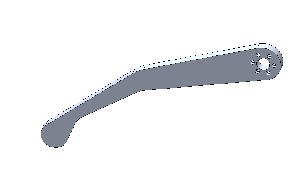
The design started by with the lower leg. To enable 360-degree rotation and to keep cost down, it was decided to opt for steppers attached to gearboxes attached to timing belts to transmit torque. Alternatively, I could have utilized higher-reduction gearboxes, like harmonic drives or several more stages of planetary gearboxes, but these solutions would have been cost-prohibitive. Transmitting torque through timing belts also provides the added benefits of providing some shock absorption to allow guard the motors from any torque spikes or being back-driven.
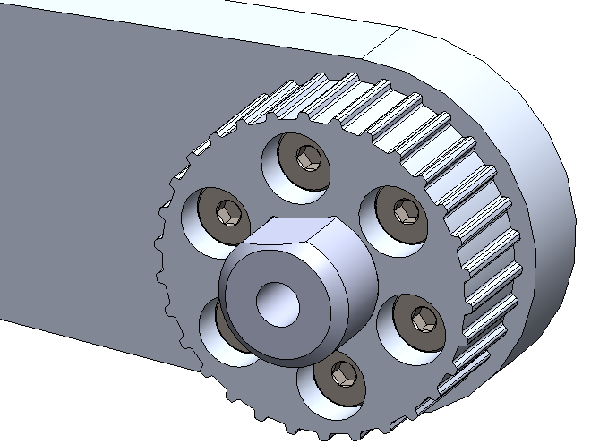
¾” D-shafts were utilized to transmit torque through the timing belt pulleys to the legs accordingly, with the matching D-profile to be waterjet into the pulleys and legs (these pulleys would be fine printed in SLS or solid FDM, or the D-shaft could be turned into a key for those who would like to replicate this design using different tools). Additionally, it was decided to attach the pulleys to the lower leg with shoulder screws to pull the assembly together and utilize the shoulders of the bolts as dowel pins to allow additional torque transmission.
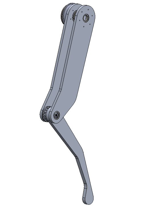
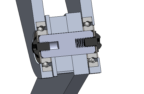
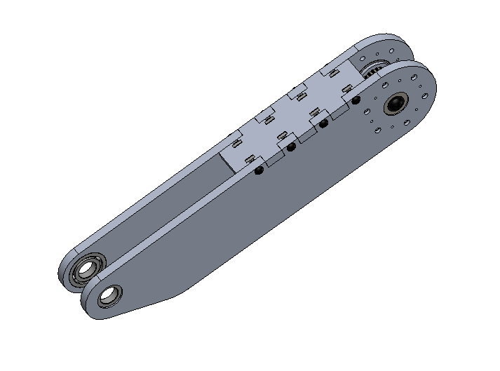
Next, the design for the upper legs was begun, beginning with the means of connecting the lower legs to the upper legs. Initially, the upper leg design incorporated only one upper leg for each lower-leg, but a second side was added to increase rigidity and reduce overall cost (a costlier crossed roller bearing would be needed otherwise to support the moment-load). Below, the start of Spike’s two-sided upper-leg assembly can be seen. An upper cross-brace was also added to help increase rigidity. The two-sided upper-leg assembly also ensures that two bearings can be used, with the design such that each bearing has both sides of its inner race captured and one side of its outer race captured (note that for bearing to work properly, you should “capture” as many sides of the races as possible to keep all the parts rigidly connected through the bearing assembly). Note how the whole subassembly is pulled together via two bolts pressing the inner races into the inner components between the bearings.
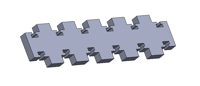
To reduce the labor needed to assemble Spike and decrease the time for Spike’s iteration cycles, joints are going to be designed in a box-joint style, where parts slot into other parts for referencing (this can be seen in the photo below). Similar to many laser-cut or milled machines from the Maker movement (like the Makerbot Cupcake, for instance), slots terminated with square holes are designed right into components to accept a bolt and a square nut, while protruding box joints and reference components for assembly. This method of design ensures that parts can come right off a waterjet or CNC mill and be immediately assembled.
Discussions
Become a Hackaday.io Member
Create an account to leave a comment. Already have an account? Log In.