 Michael G
Powering the Hips:
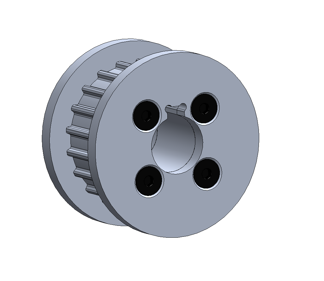
At this point, Spike still needs power to his hips. As discussed in a prior log, the two hip motors are going to be placed in the dead-space between either side’s Leg Motor Box. The hip motors are 15:1 planetary gearbox Nema 23 stepper motors, that get actual power to the hips via a AT-5 timinb belt. It’s worth mentioning here that the plan is to waterjet the zero-backlash timing belt pulleys to reduce cost. Using this manufacturing process, it’s also possible to machine the bore and a key slot to transfer the torque from the planetary output shaft to the pulley.
The plan is to have the motors arranged one-atop-another to get them in the limited space in between the Leg Motor Boxes. Accordingly, I adjusted the height of the Leg Retention panels and other side panels such that there was room for two of the stepper motors one-atop-another. I then designed another flexure motor mounting plate to clamp the two motors in place.
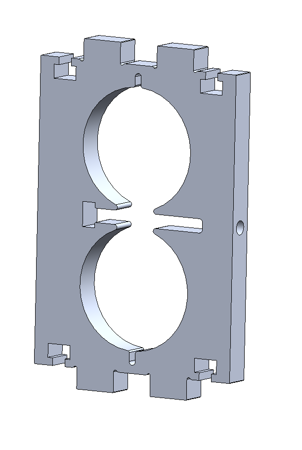
As per the standard in the design of Spike, we’re letting the machines doing the work and taking advantage of the manufacturing process of waterjet or CNC-machining. Notice how the only post-processing work necessary on this part is to drill a hole in the side of the aluminum to allow the bolt to pass through to actually clamp the motors in place.
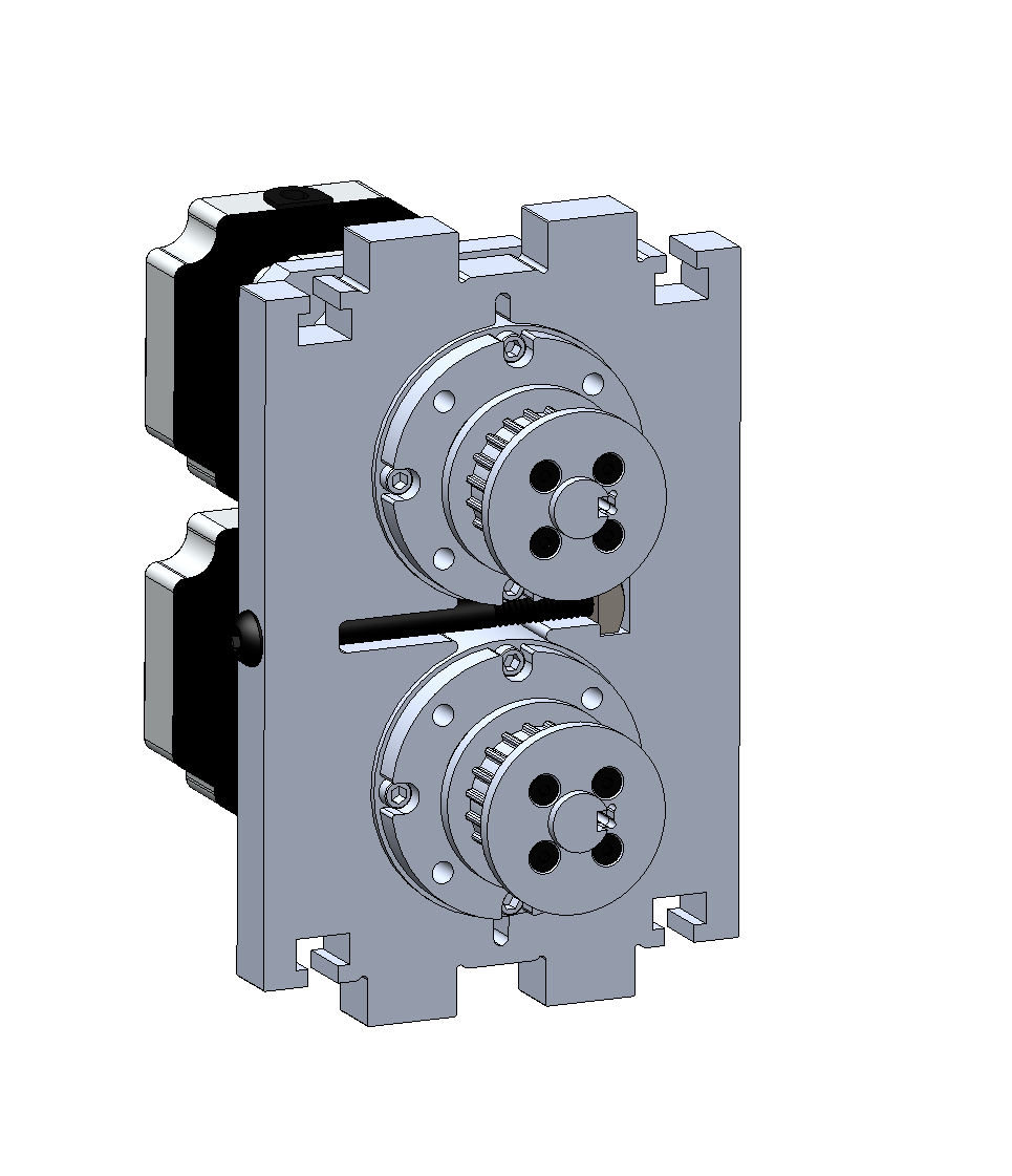
At this point I found the length of the AT-5 timing belts and mocked them up in the design. Of course, when I actually order the timing belts, they will be close to the right size, but certainly won’t be tensioned perfectly. I decided to again turn to the step-wise tensioning method talked about in an earlier log, but had to approach it a little differently to last time given space constraints. Since there won’t be accessibility to get an allen key in to screw a idler/tensioner into a tapped hole, I decided instead to use the waterjet to cut ¼” holes into the inner Leg Retention Plates.
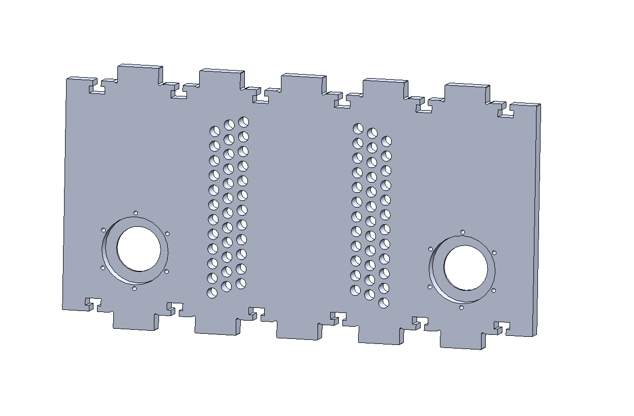
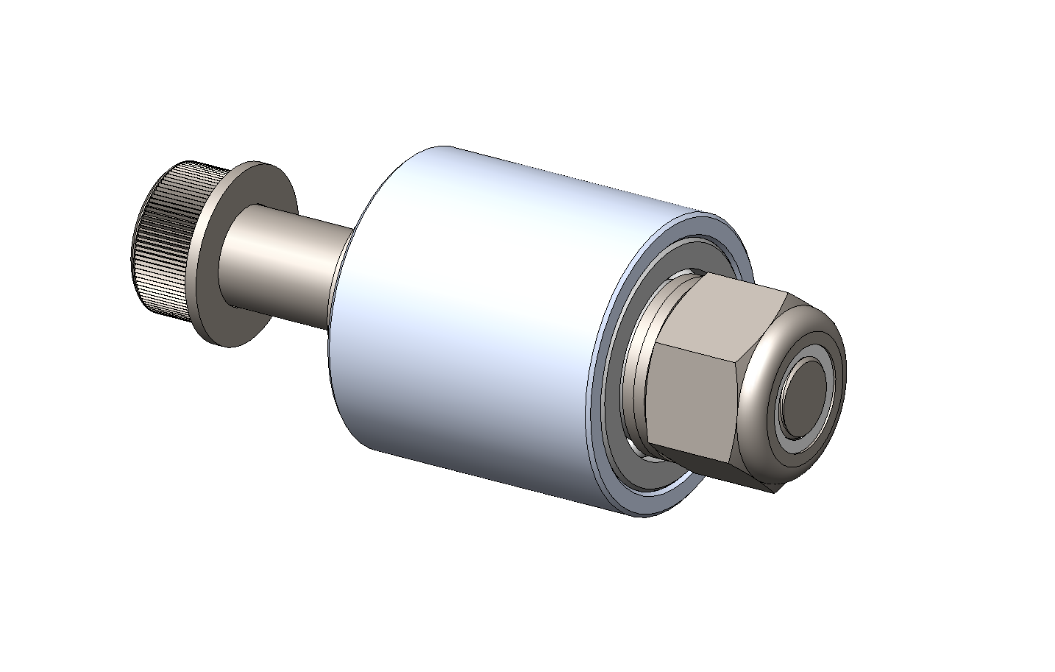
As the holes aren’t tapped, the design was changed to leverage shoulder bolts going all the way through the holes, through the inner race of the bearing, and then tightened on the end by a nut onto the shoulder bolt’s threads.
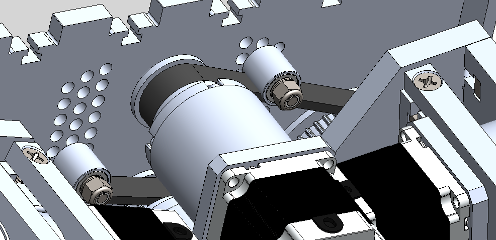
As can seen below, one of the motor’s timing belts goes to one leg, while the other goes to the other leg. The series of holes in the inner Leg Tensioning Plate allows the adjustment of tension in both of the timing belts. While the assembly is quite tight, after some adjustment, there are no conflicts between the six degrees of freedom in Spikes front or back legs.
Discussions
Become a Hackaday.io Member
Create an account to leave a comment. Already have an account? Log In.