 Michael G
Designing the Leg Motor Box:
To make it a little more clear exactly how torque is getting to the lower pulley that is attached to the side of the lower leg, I’ll start this log with some further discussion of power transmission. In the picture below, notice how the ¾: D-shaft from the upper-leg assembly goes directly through the 20mm center of the crossed-roller bearing that holds the leg assembly to the Motor Box assembly. This is such that the D-shaft can be drilled on-center to a slip fit for the outer-diameter of the planetary gearbox’s output. A slot will be milled through the side of the D-shaft above the on-center hole to allow a key to drop-in to the transmit torque from the keyed shaft of the planetary gearbox output to the upper-leg D-shaft.
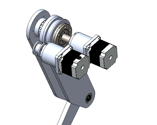
Recall from previous logs that the upper-leg D-shaft, unlike the lower-leg D-shaft, does not serve to mount the upper leg to the Motor Box Assembly, as such is achieved via the crossed roller bearing. The D-shaft instead only is meant to accept torque from the planetary gearbox and transmit that torque (via the D-shaft) to a pulley. One notable down-side of this design style, in addition to design complexity, is that when the upper-leg moves, the lower-leg will not completely move translationally with the upper leg (the lower-leg will rotate one way or the other relative to the upper-leg if only the upper-leg motor moves). However, this can be completely counteracted in software.
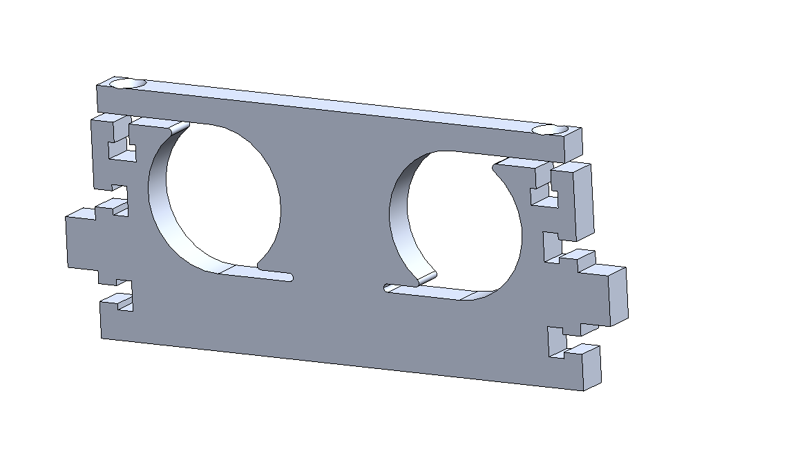
After I had the basic concept getting power to the legs, I began to flush out the design of the Leg Motor Box Assembly. The Leg Motor Box Assembly was designed to be completely waterjet, with box-joints and slit and square-nut assembly. The design for the Leg Motor Box Assembly began with two waterjet plates, one to mount to the crossed roller bearing and one to provide a motor mounting plate. I also decided to leverage the manufacturing process of waterjet by using a flexure to mount the motors while minimizing part count. A flexure is essentially a component that is designed to bend or flex in one or more directions to replace some form of actuation – in this case, cutting strategically cutting slots in the Motor Mount Plate in the Leg Motor Box Assembly, which clamp onto the motors to keep them in position when two bolts are tightened. I then added two side plates to connect the first two plates into one subassembly.
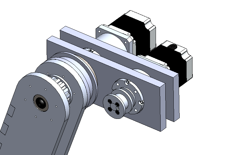
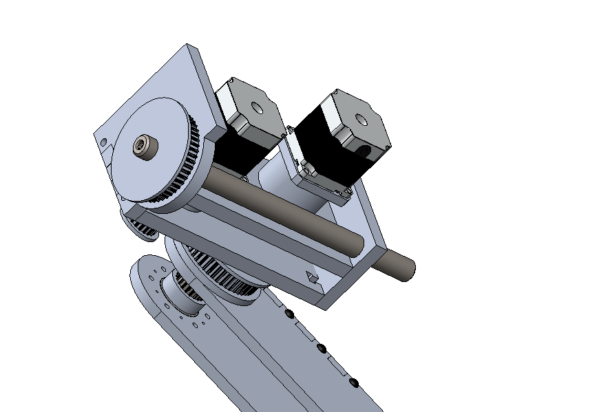
A ¾” D-shaft was also added, going through the two Side Plates in the Leg Motor Box Assembly; the D-shaft was is locked from rotating by a waterjet D-shaft profile in the side plates. Further, one of the side plates is larger than the other to accept a waterjet timing belt pulley. This pulley, analogous to the pulleys discussed previously, has a D-shaft profile cut into it, with additional torque-transfer and assembly with shoulder bolts. Just as with the other two degrees-of-freedom per leg, the hip joint will be powered by a stepper to gearbox to timing belt system. In this case, however, the hip motors will be mounted directly to the body of Spike.
Discussions
Become a Hackaday.io Member
Create an account to leave a comment. Already have an account? Log In.