 Arduino Enigma
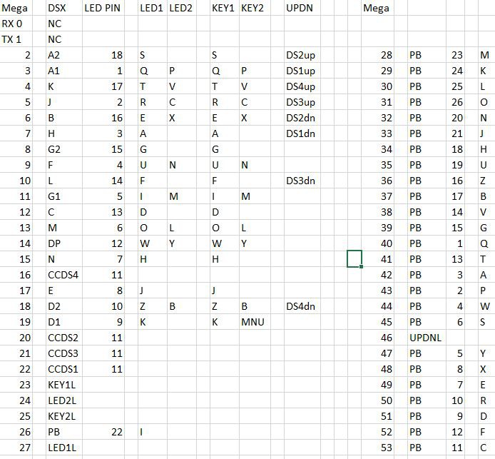
The pin assignments have been traced and double checked. Each LED and switch on this board can be uniquely addressed with two microcontroller pins.
This simulator uses a fairly conservative multiplexing design to light up the LED and read the keys. There are a lot of different devices on each pin, but that is solved in software by controlling each device at a different frequency. The 16 segment displays need to be driven more frequently to eliminate flicker. The keyboard can be read one key at a time when switching from one sixteen digit display to another. The lampfield can be treated like another sixteen segment displays and if needed, multiple lamps can be lit simultaneously.
Here is a detailed schematic for one row, pin 3 is selected because it has 6 devices. Other lines may not have anything connected on LED2L, KEY2L or UPDNL (schematic made with the Klunky Schematic Editor https://www.qsl.net/wd9eyb/klunky/home.html)
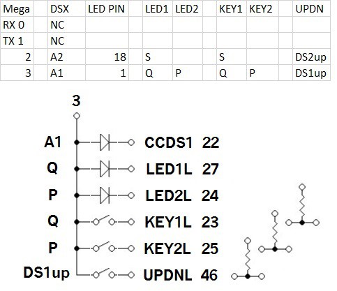
Pin 3 controls one side of:
1) Segment A1
2) Lampboard letter Q
3) Lampboard letter P
4) Keyboard letter Q
5) Keyboard letter P
6) Up Key for Digit 1
Here is the algorithm to illuminate and read all of the devices (although not at the same frequency)
1) put the correct bit pattern on A.. H segments for digit 1 (active high). In order to control the brightness difference between letters with a lot of segments and letters with few segments, this task can be subdivided in two by putting the bit pattern for 8 segments first, then putting the pattern for the other 8 segments.
2) make the CCDS1 line active low to illuminate the first 16 segment digit. Make CCDS2..CCDS4 high or inputs to prevent anything from showing in digits 2..4
3) make the LED1L and LED2L lines high or inputs to prevent anything from showing in the lamp field.
5) Wait 400uS or execute an Enigma encoding task that takes less than that time to execute.
6) Make all the segments 1 in preparation to read the keyboard
7) Make 1 segment low, start with A1, on next iteration, select A2...
8) Read KEY1L, if 0, Q is pressed
9) Read KEY2L, if 0, P is pressed
10) Read UPDNL, if 0, DS1up is pressed
11) repeat step 1, but activate CCDS2 to illuminate the second 16 segment digit. When all four 16 segment digits have been illuminated, repeat step 1 again but activate KEY1L, then repeat one more time with KEY2L
Here are the tasks one at a time:
1) letter pattern (active high)
2) CCDS1 (active low) and wait 400us
3) Read one set of keys (set one segment to low and read KEYxL for low)
4) letter pattern
5) CCDS2
6) Read next set of keys
7) letter pattern
8) CCDS3
9) Read next set of keys
10) letter pattern
11) CCDS4
12) Read next set of keys
13) lampfield pattern
14) LED1L
15) Read next set of keys
16) lampfield pattern
17) LED2L
18) Read next set of keys
It looks like a state machine will take care of the multiplexing.
Discussions
Become a Hackaday.io Member
Create an account to leave a comment. Already have an account? Log In.