 alessandro verdiesen
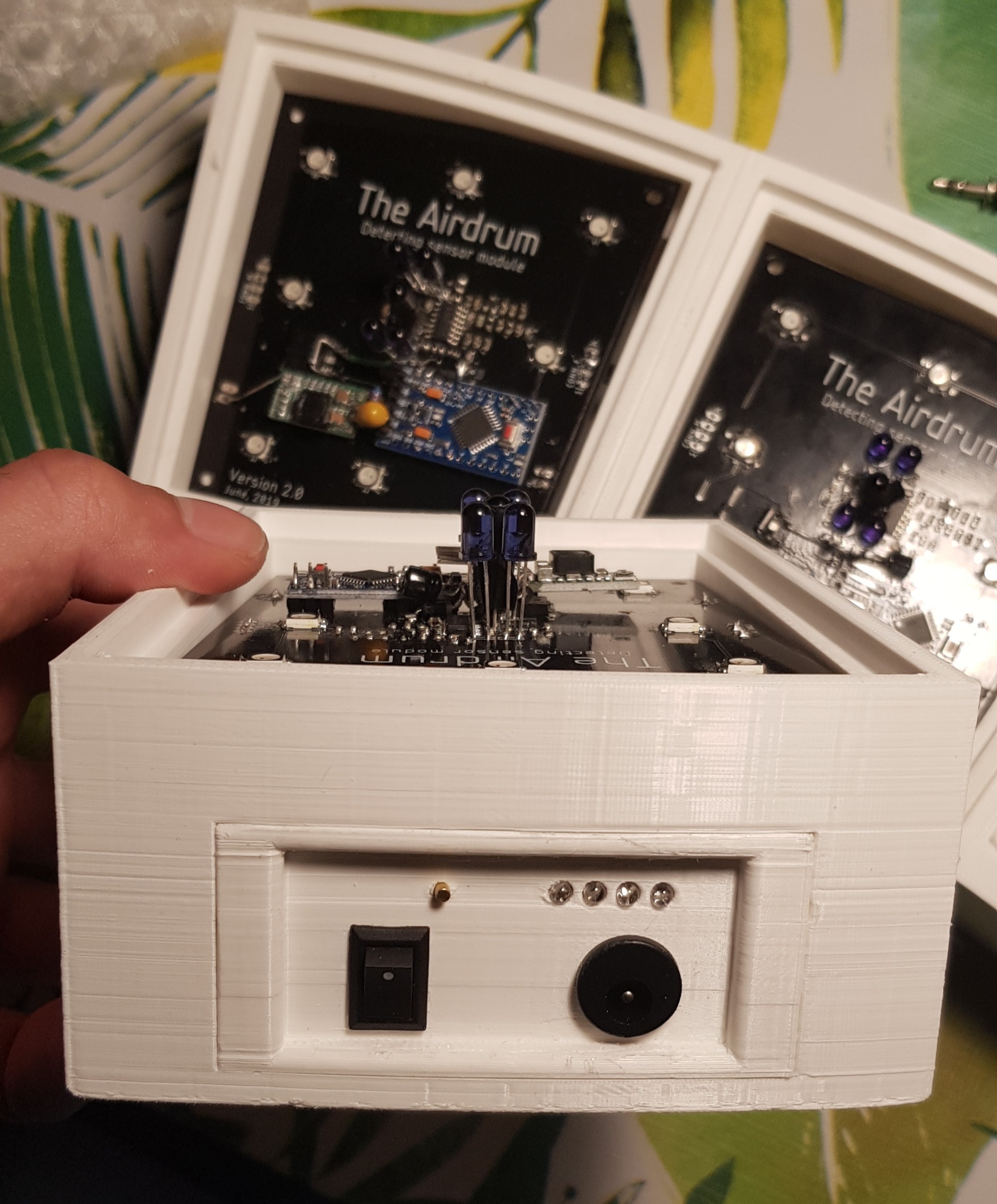
Meet The Airdrum V2 !
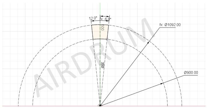
The new version is fully modular, has a greater range, has faster response time and can be built into a full circel :)
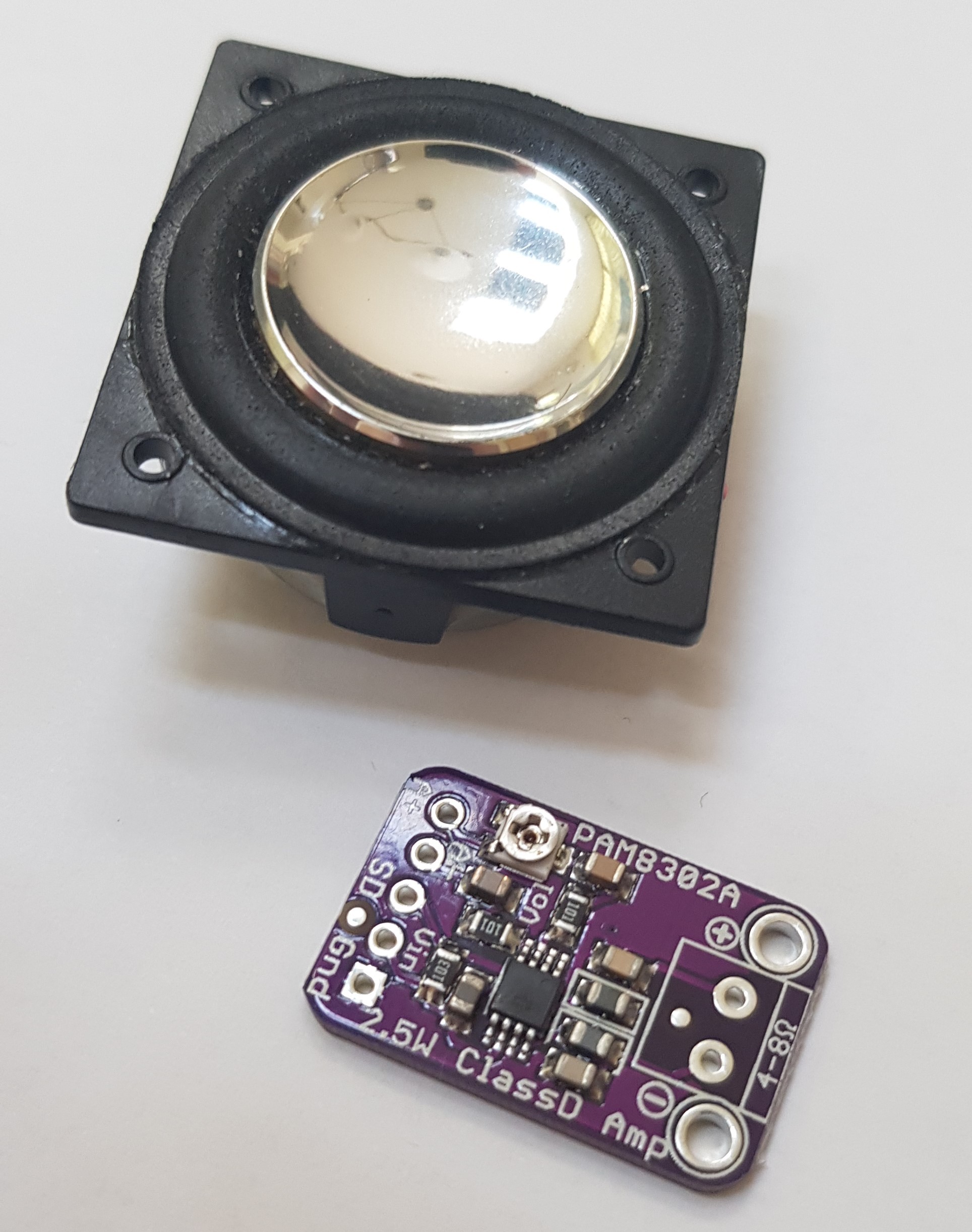
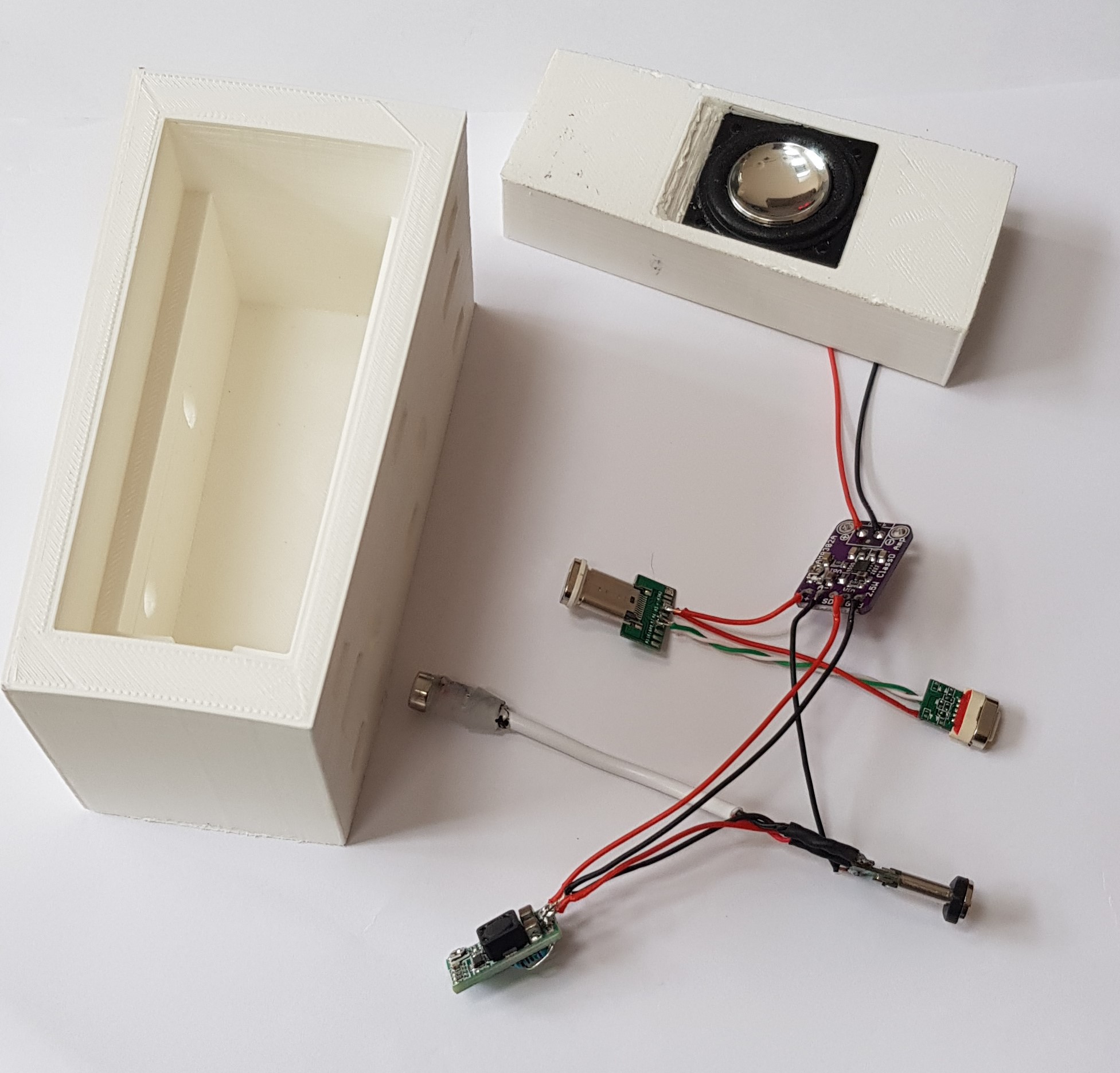
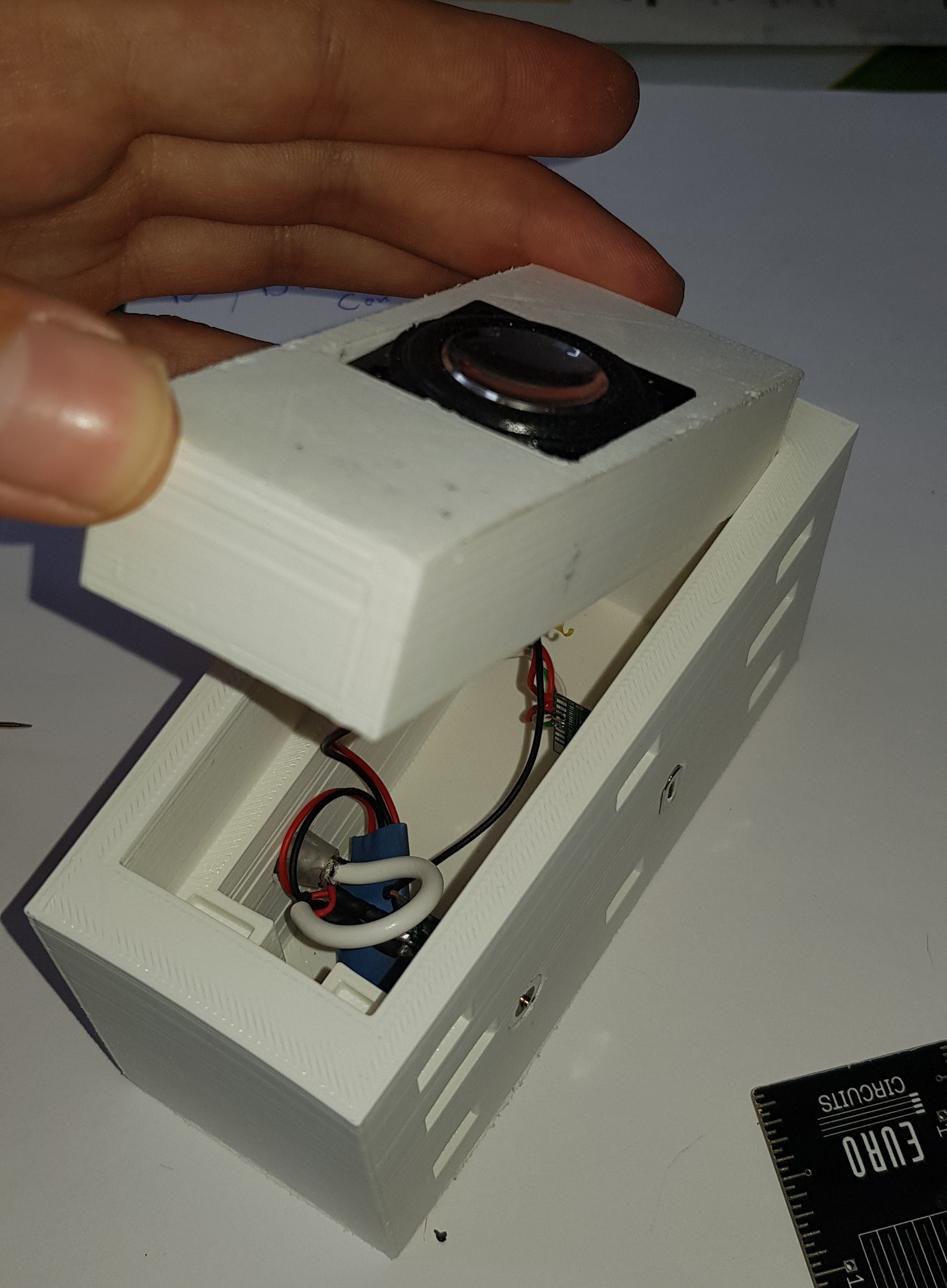
Playing a MIDI file on Rpi3 with the speaker modules
This video demonstrates the speaker functionality with playing a song from a midi file on the Raspberry pi using Fluidsynth. (The hand movement is just for fun)
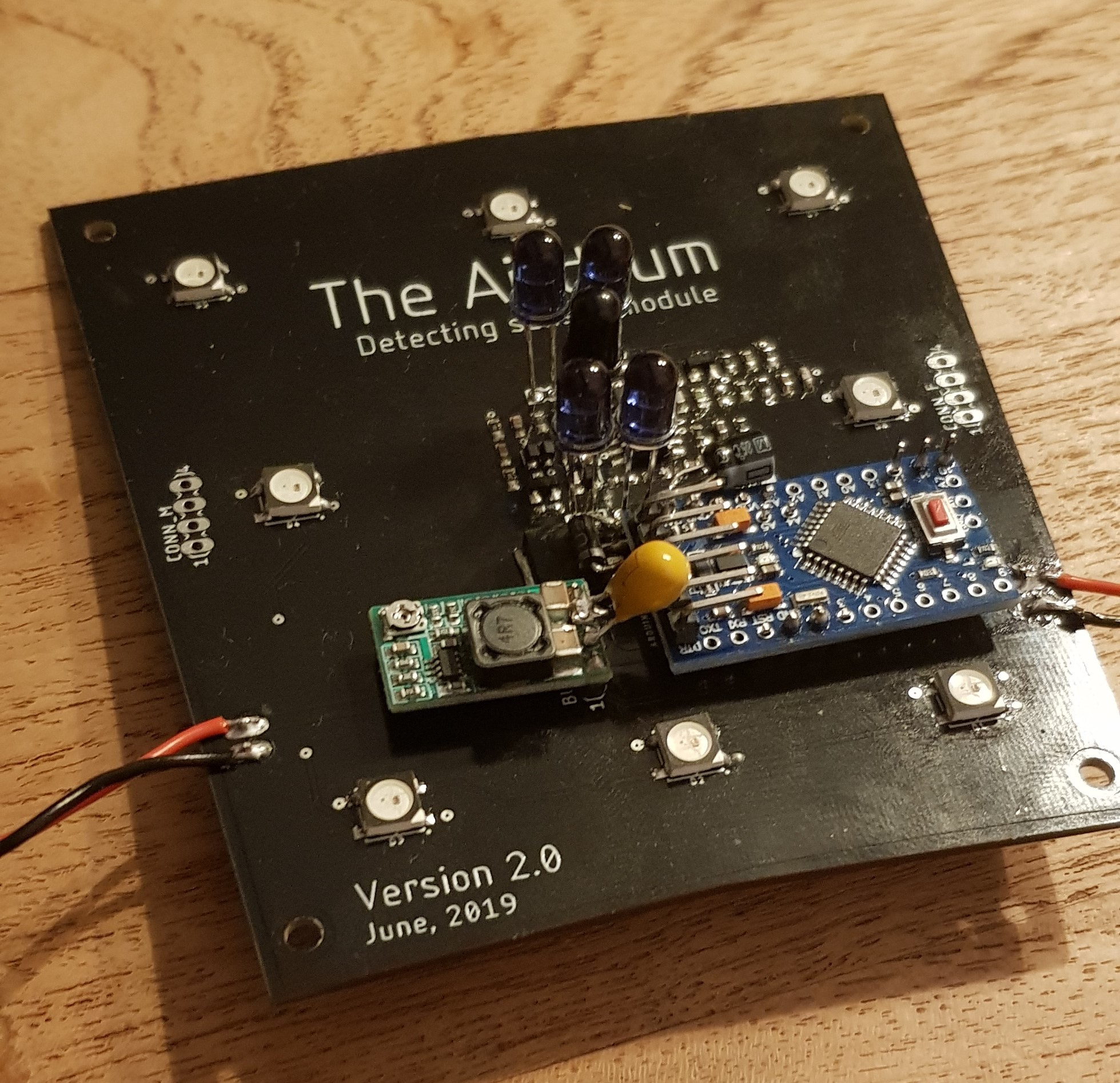
The Airdrum is powered by a power supply for demonstration purposes. It shows that we are running the system at 15.5 Volt with a consumption of +-0.6 Amps
Video of V1 for reference
(Depreciated version. V2 is being engineered)
Why?
We talked with therapists and health care institutions during our research. These Health care institutions (which facilitate housing, learning opportunities and day care for severe disabled people) often encounter the difficulties of communicating with their clients. The institutions experienced that making music together is a great way of communicating and this is why many institutions offer music therapy. These music therapists say that clients are evidently learning and, more importantly, having fun while making music!
Unfortunately, clients are not always able to play traditional instruments because of their mental and physical disabilities.
Contributions to society
According to music therapists, the main goal is having fun. It is proven that people learn more when having fun. When playing an instrument, and particularly the Airdrum, clients can share emotions, practicing their motor skills end learn to listen and watch. All of these benefits are possible by having an instrument that is able to produce auditve and visual feedback with minimal input of the user.
Goals
We have four goals concerning the development:
- Accessible
We want everybody to play and interact with the Airdrum. Varying from people who are to experience their first musical device to the professionals, who can use the airdrum as input to their compositions.
- Affordable
While exploring the various specialized instruments for the above mentioned audience, we found out that these are very expensive. Often even more expensive than professional electronic or acoustic instruments. We want the Airdrum to be played for a broad audience so price must be a concern.
- Adjustable
We want the Airdrum to be as versatile as can be. It must be possible to choose (custom) sounds and lights to play.
- Modular
Everybody can built the amount of panels they need / want.
With the minimum at 2 panels; Rpi motherboard and a batterypack panel.
Plans for further improvement
With accessibility, affordability, adjustability and modularity in mind, we want to implement the following ideas for the next build logs:
- Create a working prototype
- Built in synthesizer
- Connecting the prototype with a smartphone or tablet
- Designing an app
- MIDI possibilities
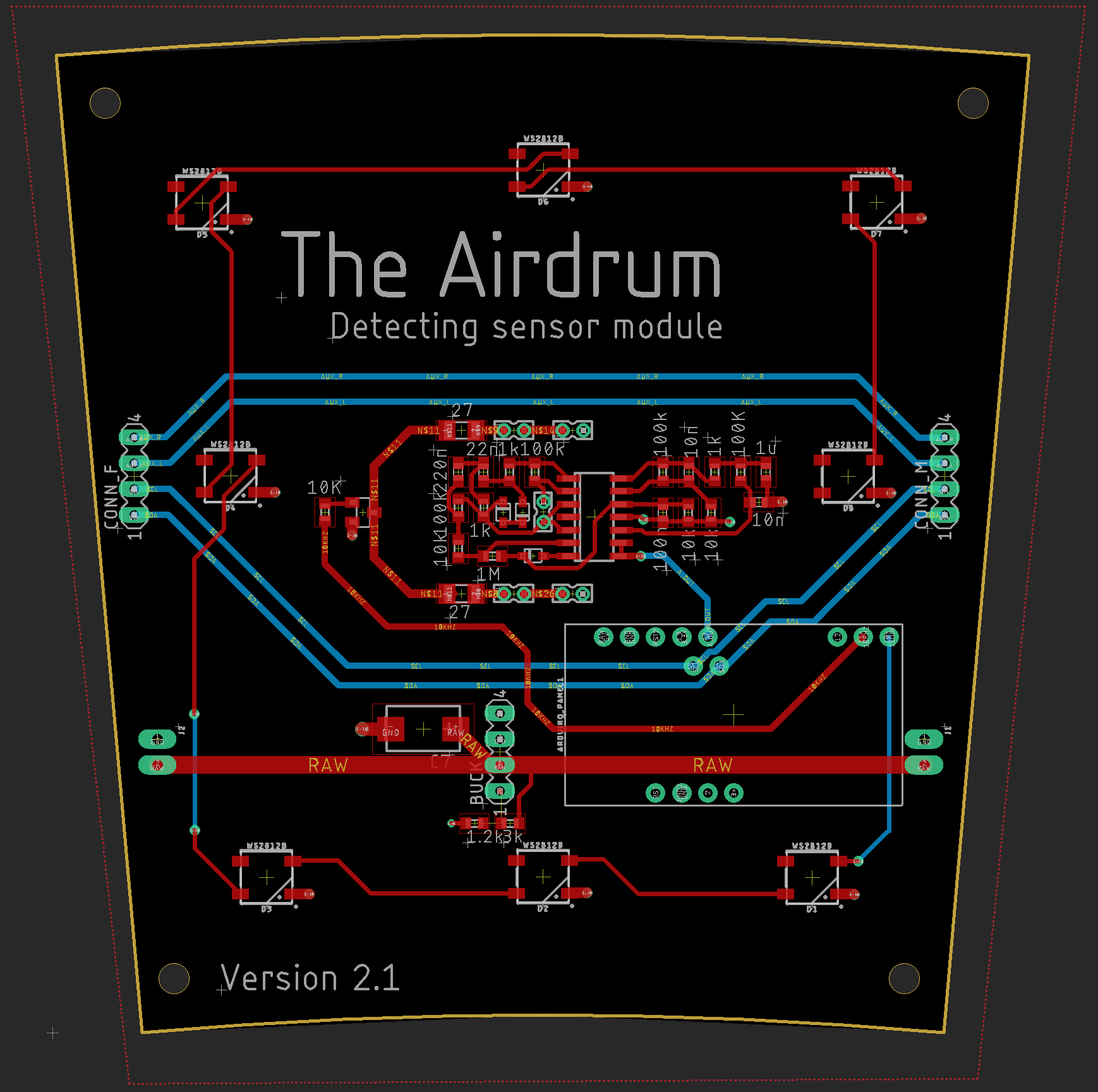
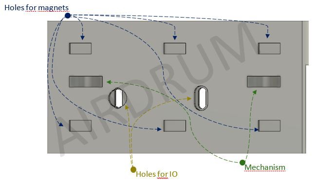
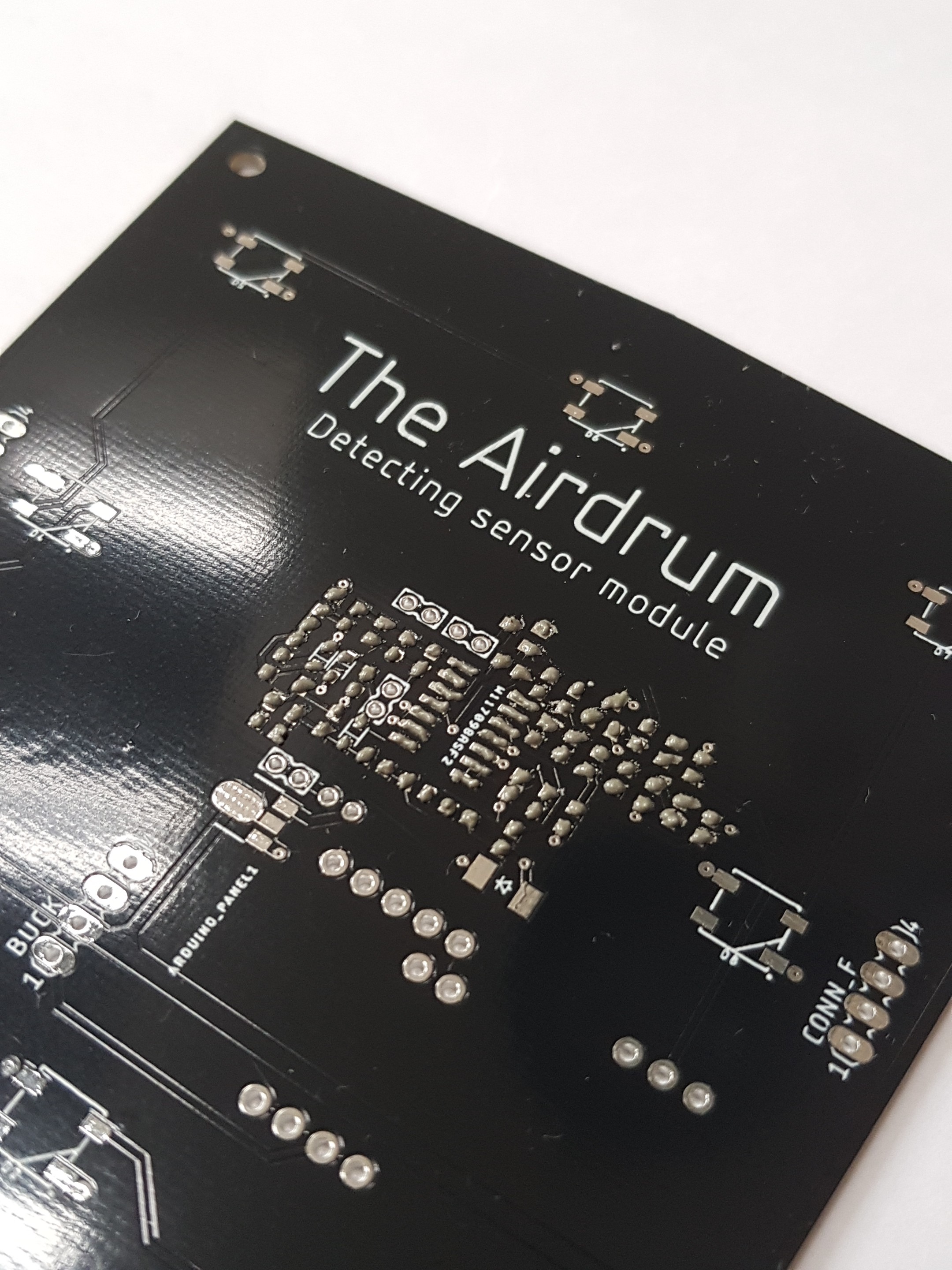
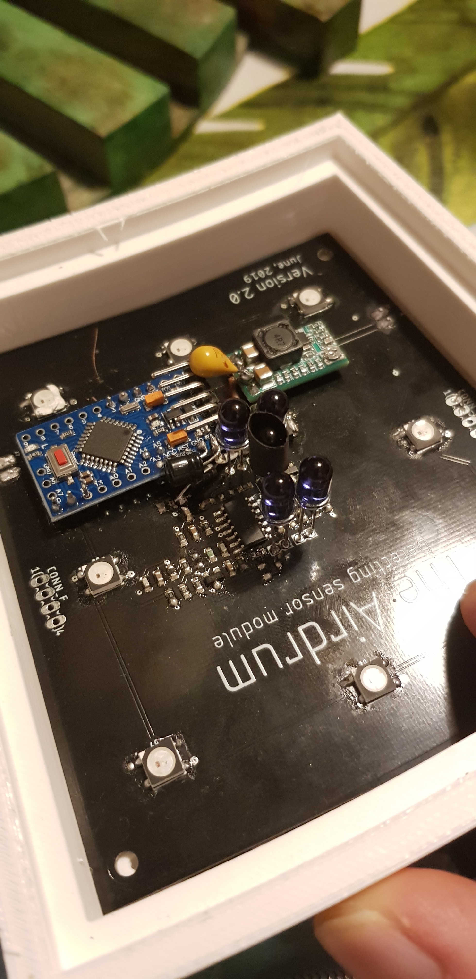
High-level overview of The Airdrum V2.0
We went full circle in the version2.0
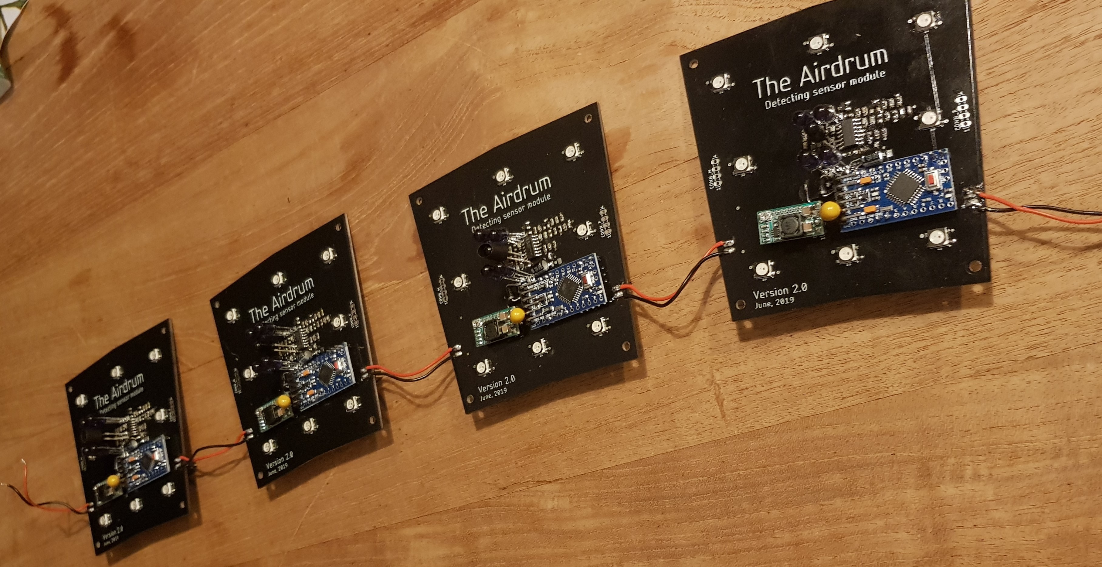
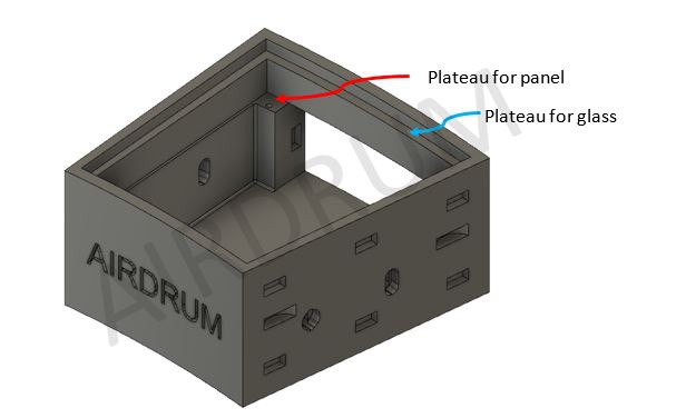
As seen in the picture below, users need a minimum of 2 panels and 2 speaker modules to get a fully functionable and portable Airdrum. (more details will be given in the logs)
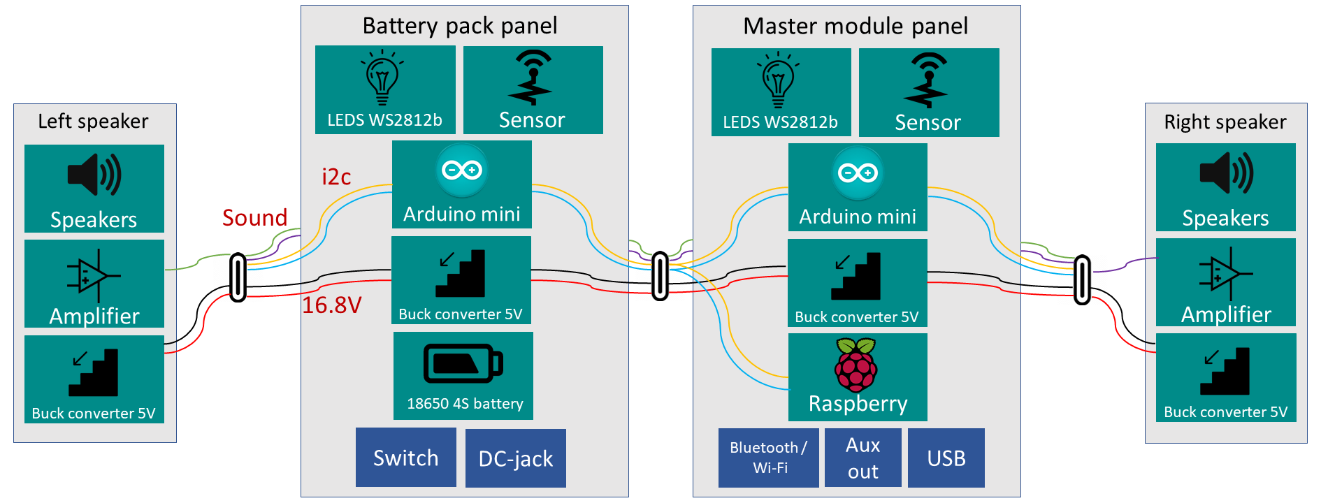
All panels will include a Buck converter....
Read more »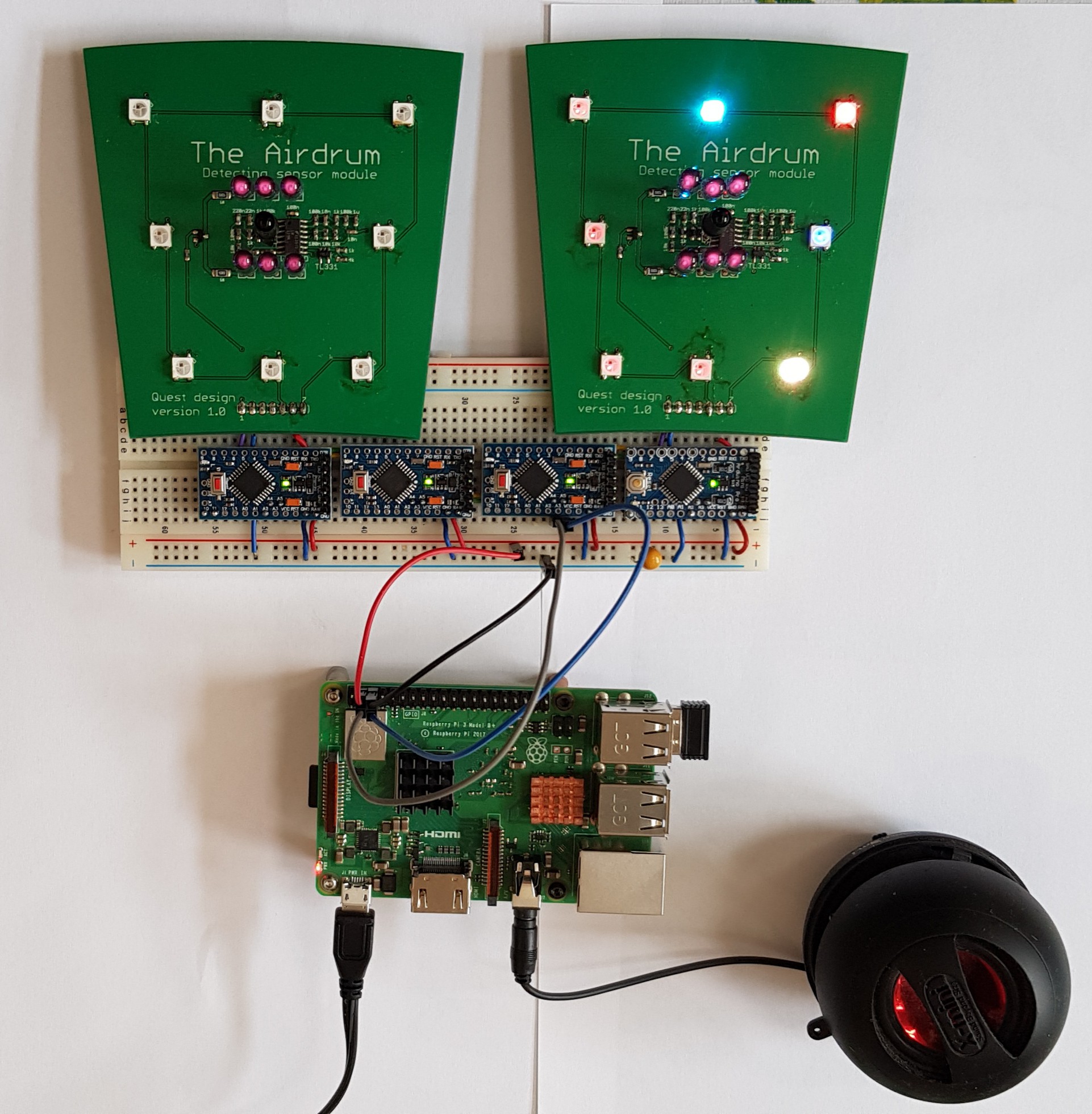


 David Cook
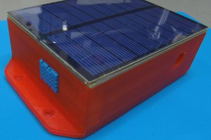
 Mile
Mile
 Gorky
Gorky
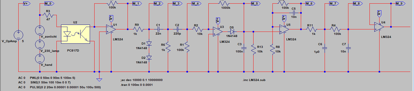
Hi, I'm wondering how your IR sensing circuit compares to the distance sensors like the ones that Sharp make (e.g. the GP2Y0A41SK0F). Do you have an idea of the min/max distances you can measure?