 alessandro verdiesen
The board
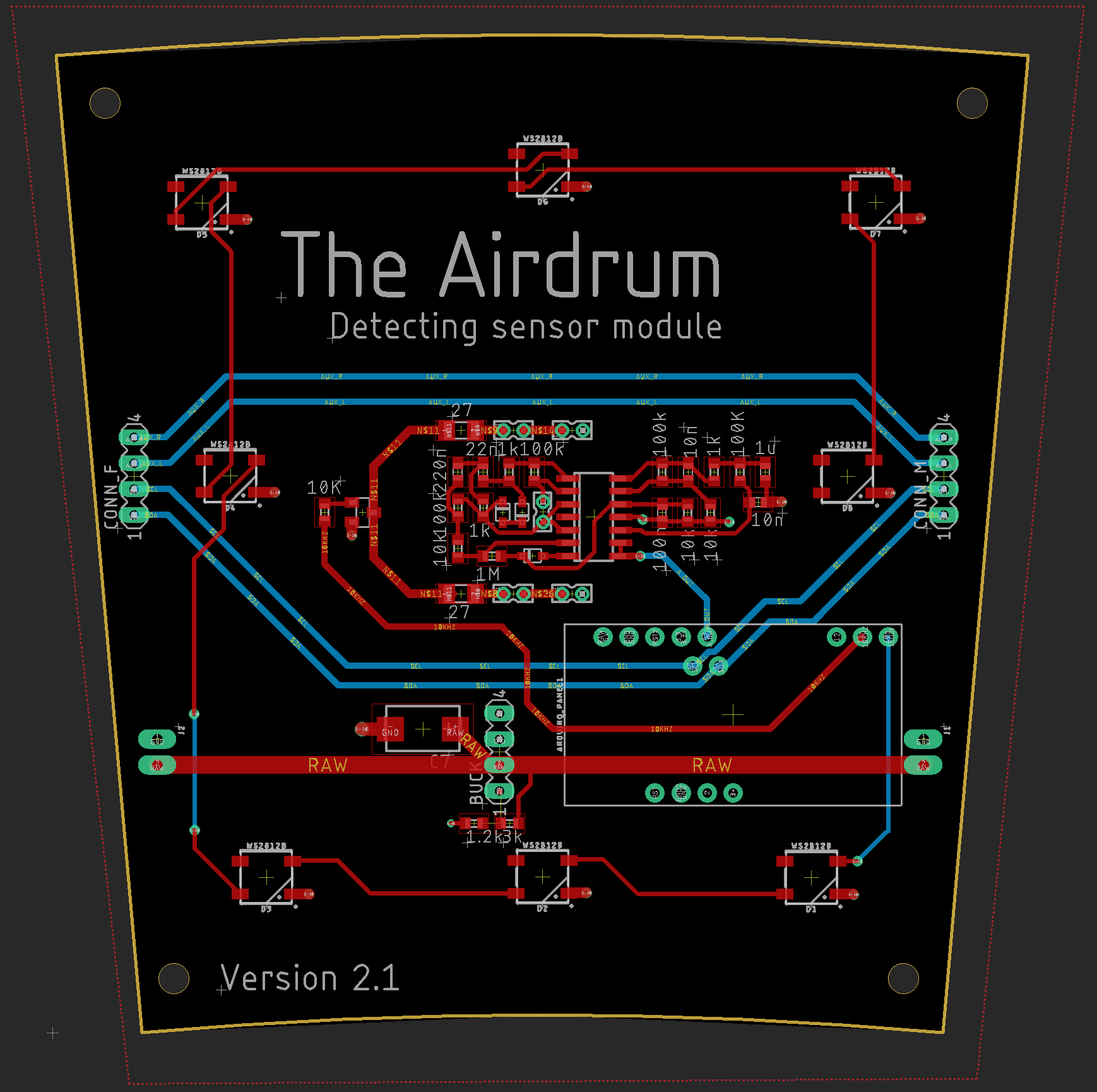
After designing the schematics in LTspice we designed the pcb in Eagle. With the modular design in mind we decided to go for a PCB with it’s own processor and Buck converter.
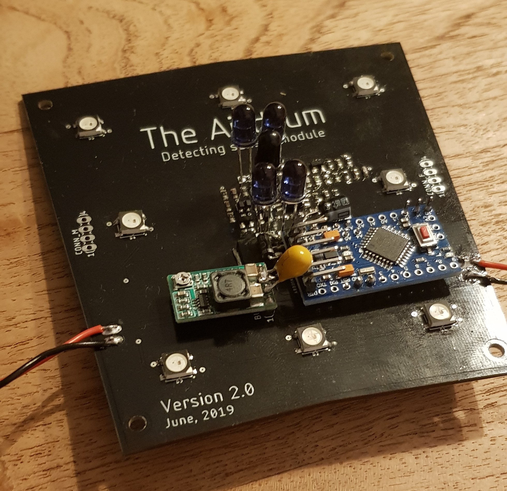
The Pro mini is placed to make the panels individually addressable for data transfer to the master synthesizer. It will drive the IR-Tx LEDs, drive the WS1228B digital RGB LEDs and read the analog input coming from the analog detection sensor.
The Buck converter is placed to reduce the current through the 16V power lines of the panel.
The PCB is 10 degrees in width to be able to fit in the casing and the RGB LEDs are placed like the previous version.
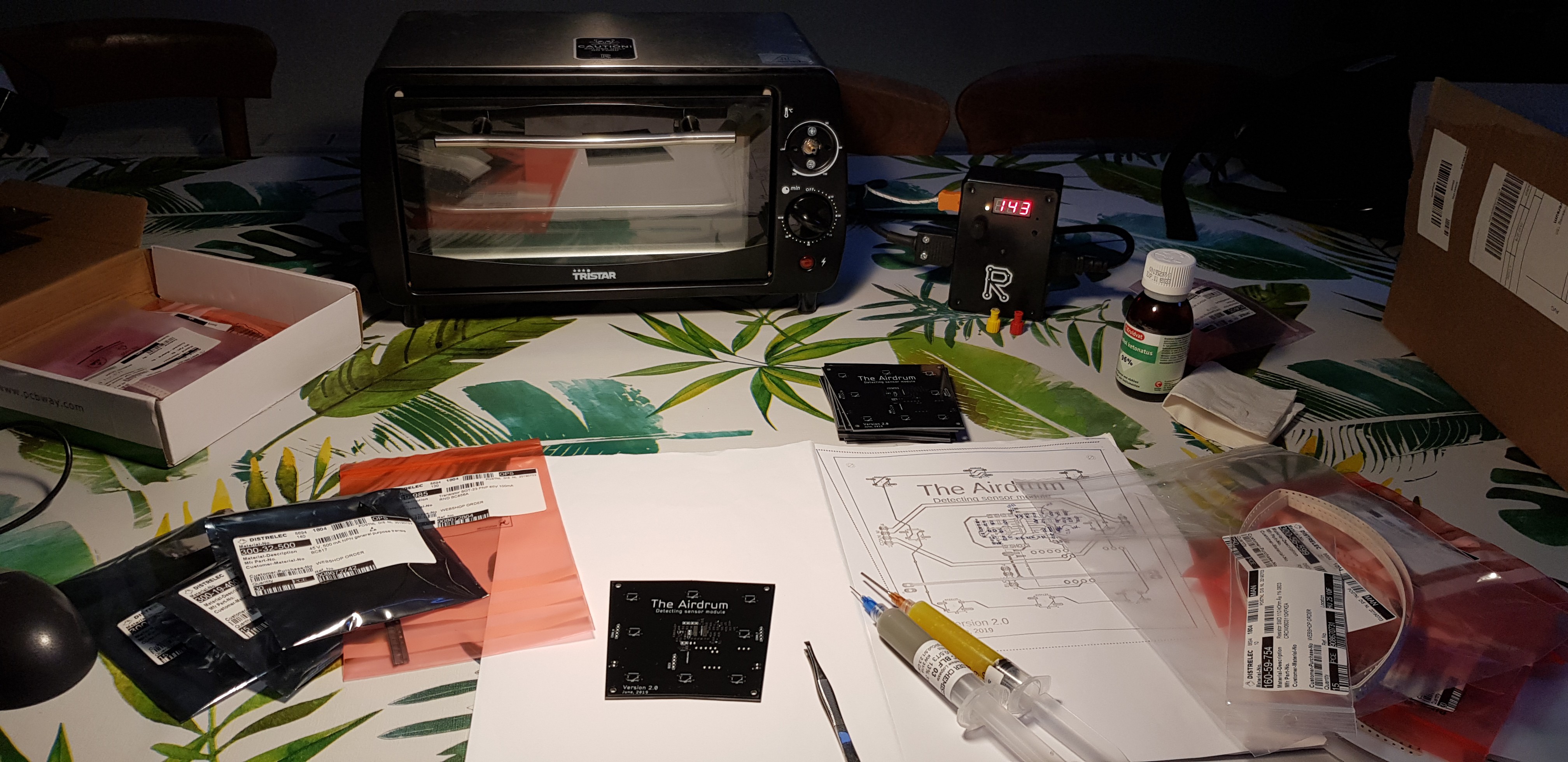
Placing all the components and reflowing the solder paste.
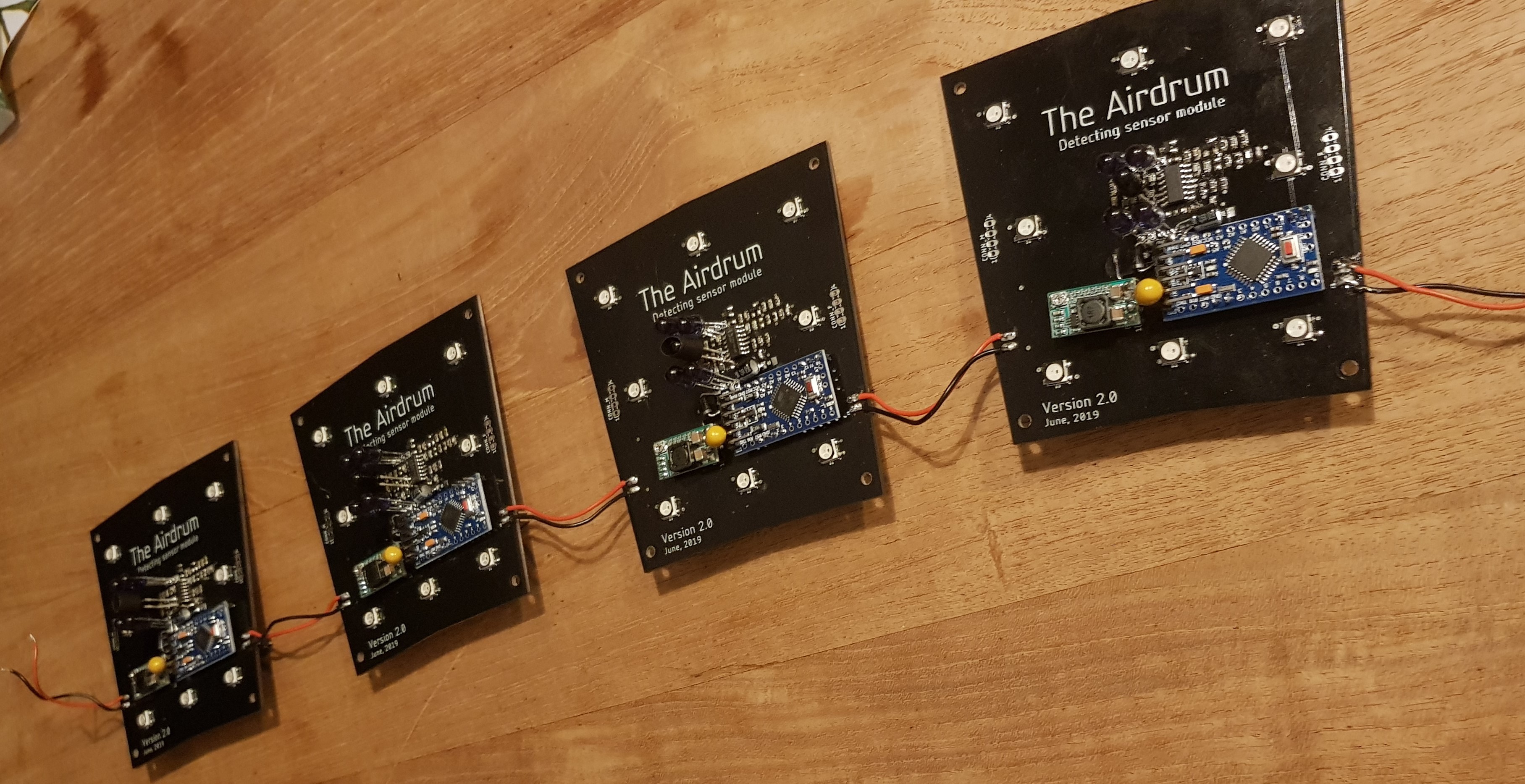
First 4 prototypes
Decoupling capacitor
When coupling or decoupling a panel to The Aidrum the power lines will get voltage spikes. To protect the circuits for these electrical transients we have placed a 22 µF tantalum capacitor over the RAW and GND lines of the panel. This capacitor wasn't placed on the board we ordered, but it is placed in the uploaded V2.1 schematics.
16V power line
Each slave panel (No Rpi3) uses 100mA when the Tx IR Leds are sending. The panel with the RPi3 included draws around 300mA. For this prototype the decision has been made to order PCB’s with a copper thickness of 1oz/ft2 to reduce the cost per panel.
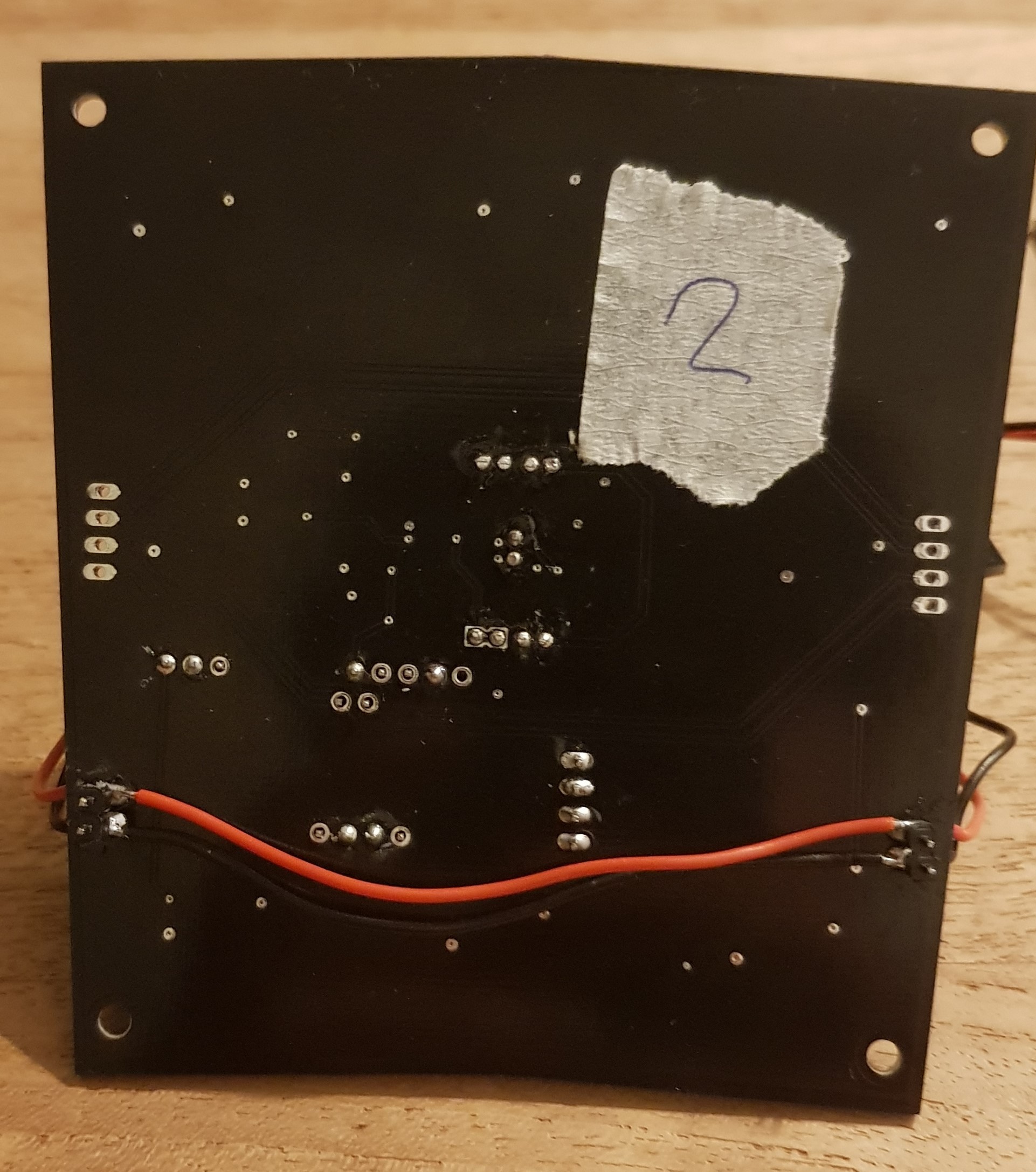
Even in a single battery, almost full circle configuration (one missing panel in the full circle, therefore making the longest battery-panel trail) the width of the RAW traces are enough to power all panels. This is excluding all the magnetic connectors and USB-C converters in between the panels. To reduce the voltage drop in the power lines we have included an extra wire beneath the PCB.
Discussions
Become a Hackaday.io Member
Create an account to leave a comment. Already have an account? Log In.