 DailyDIY
I started the idea with imagining how the user would like to interact with the device and what would their experience be.
Based on a mental idea of how I would like to use it
1) I expect the device to work twice a day for a month, without needing to charge.
2) I expect to know the exact temperature my beverage is at.
3) I should be able to clean the device easily and with running water.
4) It should not be heavy at all, and should weigh roughly about a pencil.
5) It should have the form factor of a stirrer.
6) It should be able to adapt to every known kind of tea/coffee mug available around me.
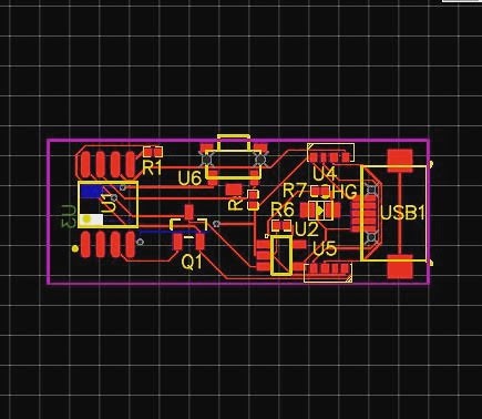
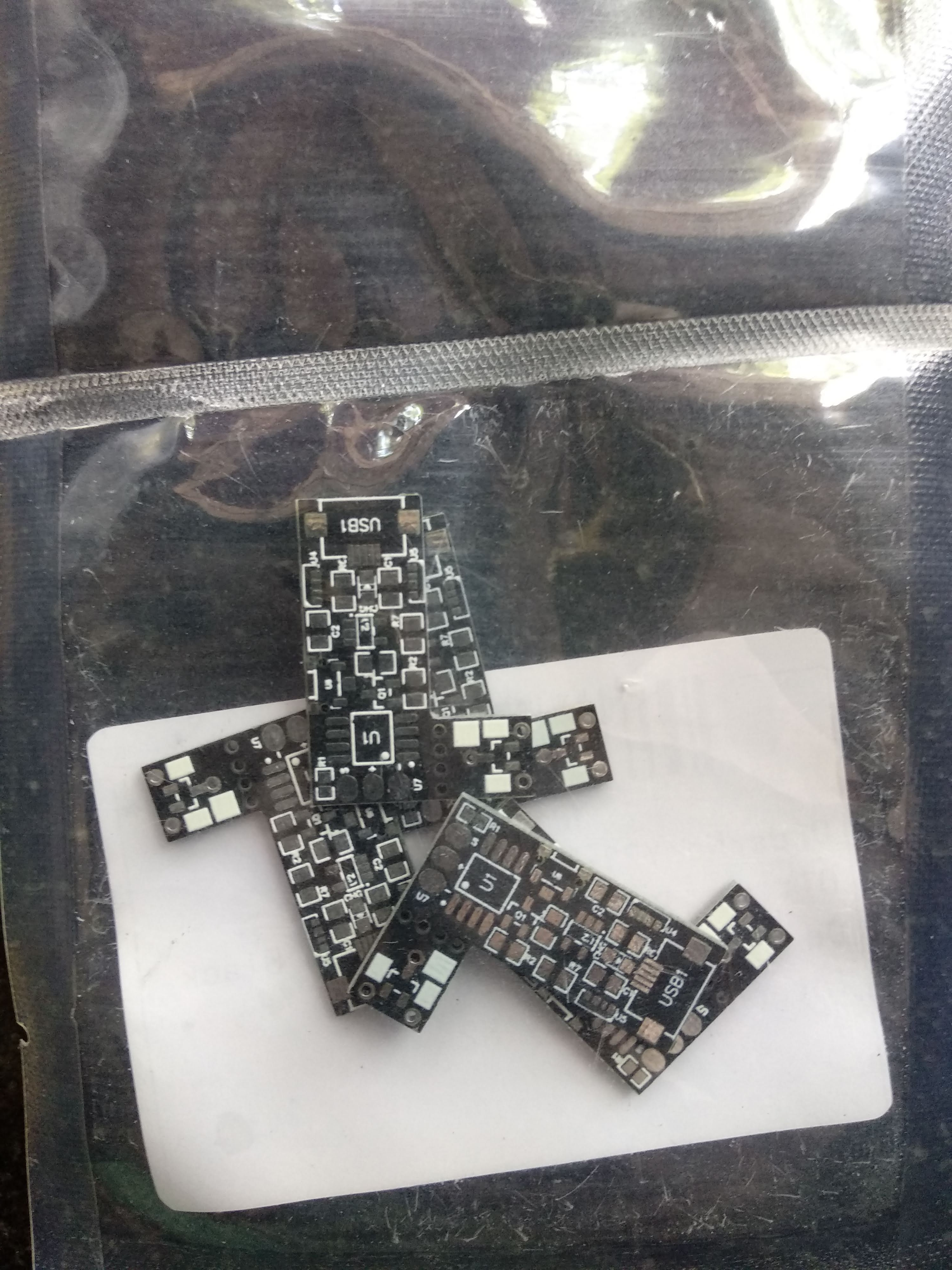
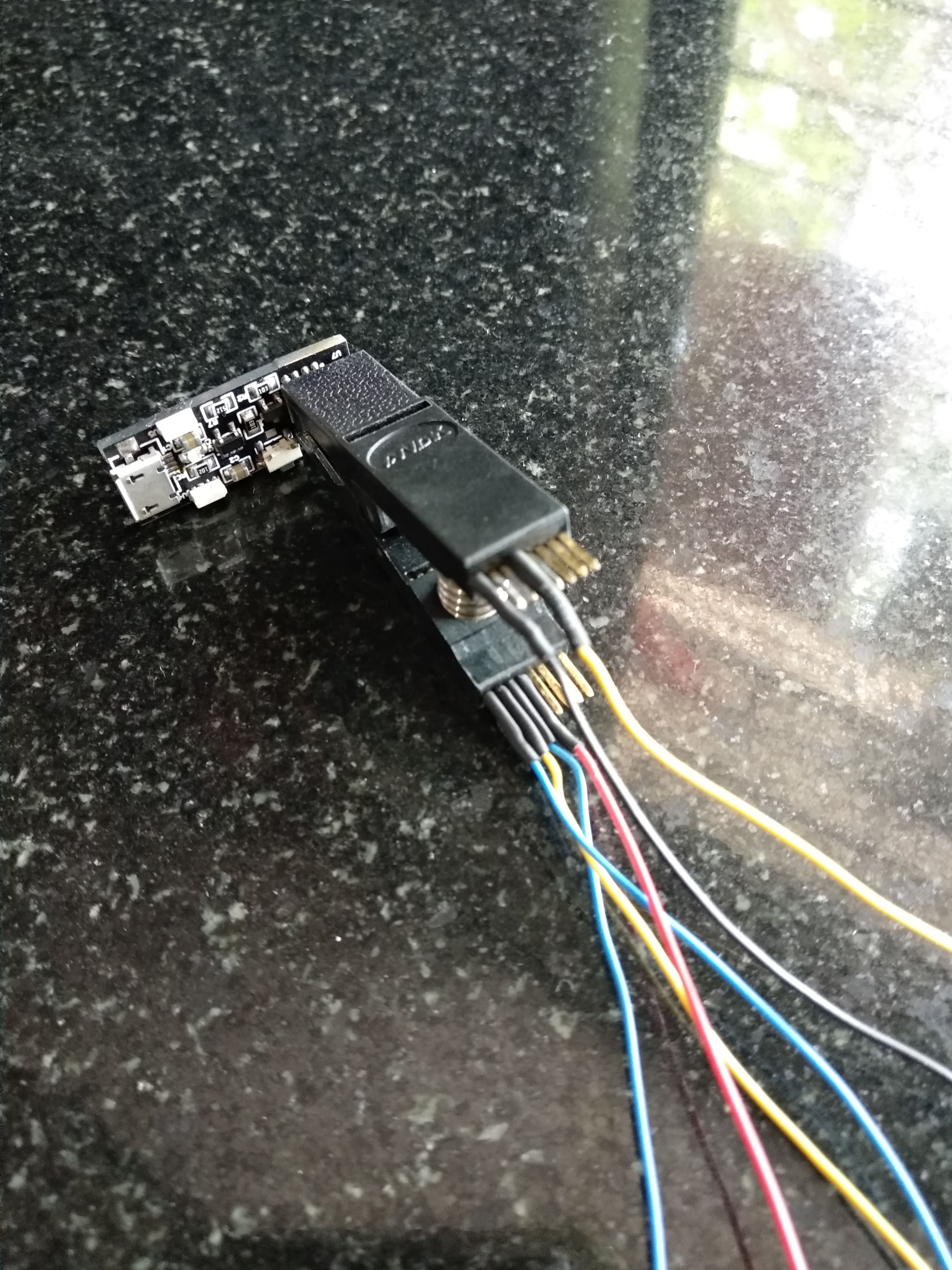
Some of these were easy to meet( based on experience), but some were big question marks. Nevertheless, I started to order parts and put together a basic working circuit i could test and refine my code.
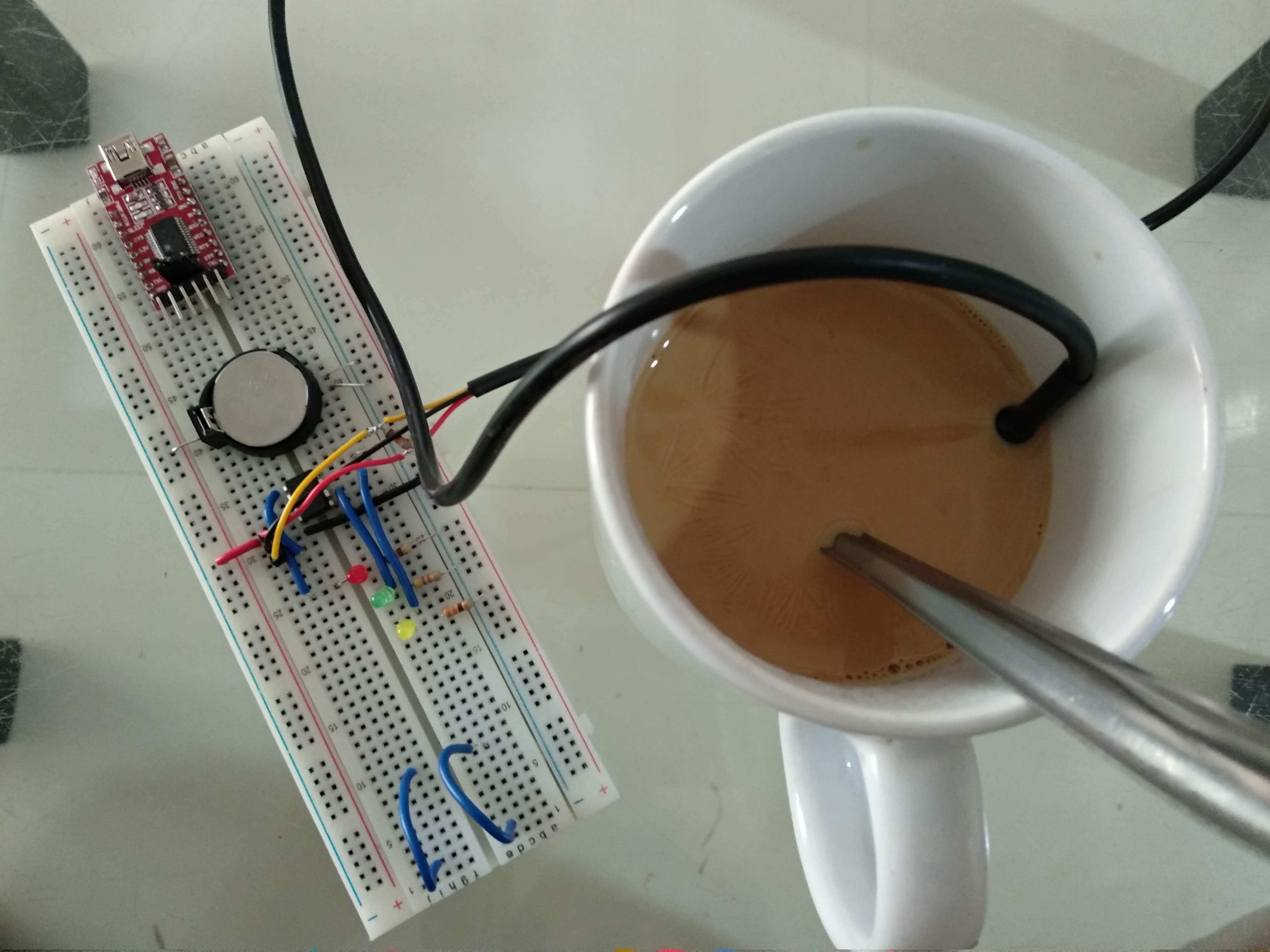
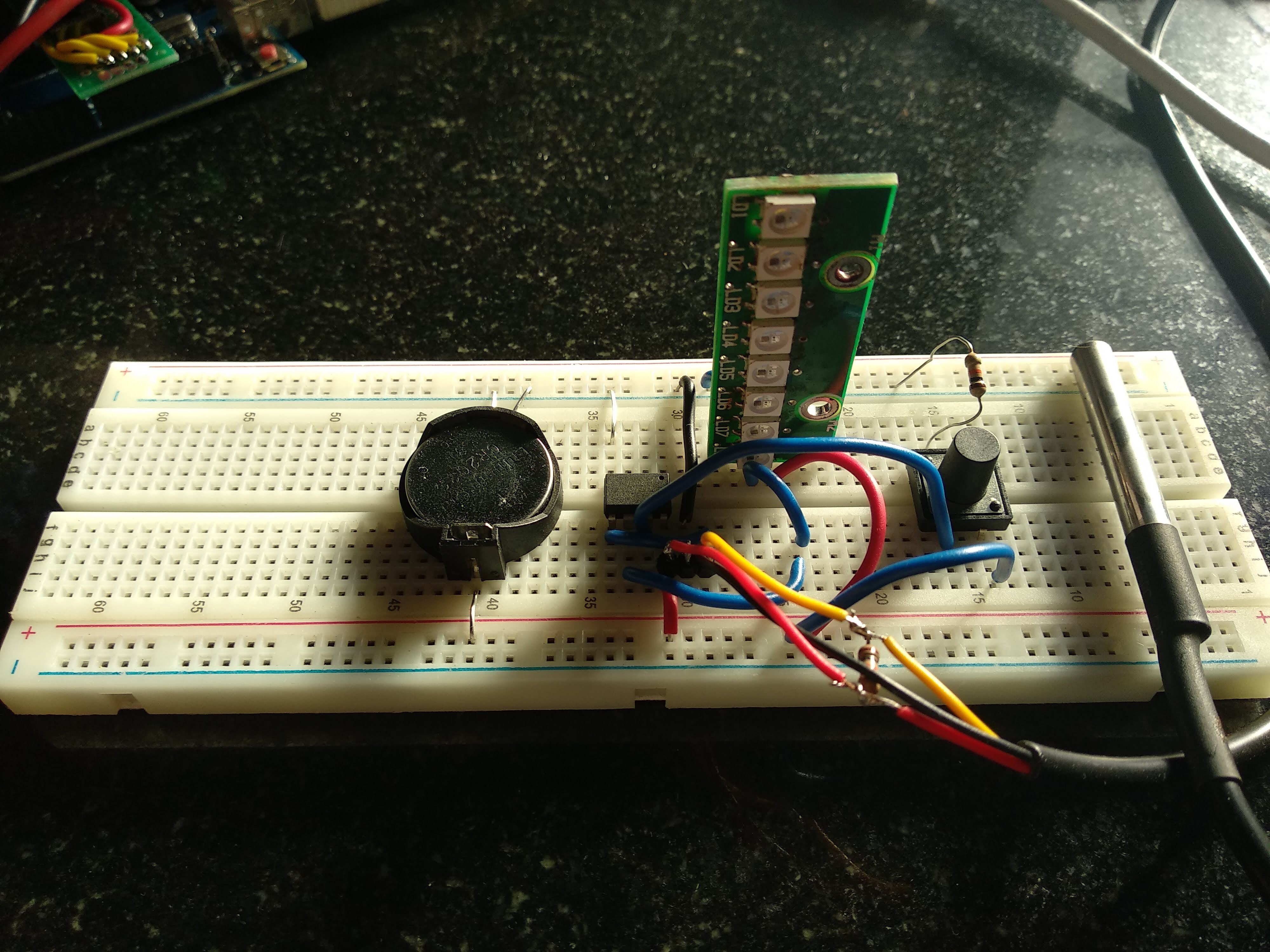
I initially thought of not putting a Li Ion Battery because of export restrictions and certifications I would require to go through. I planned my design around a CR2032 battery.
The battery ran for quite a few days before it drained and was rejected as the product size was starting to get cumbersome.
My initial prototype was also with a Red, Yellow and Green discrete LED tied to the I/O pins of the Attiny85.
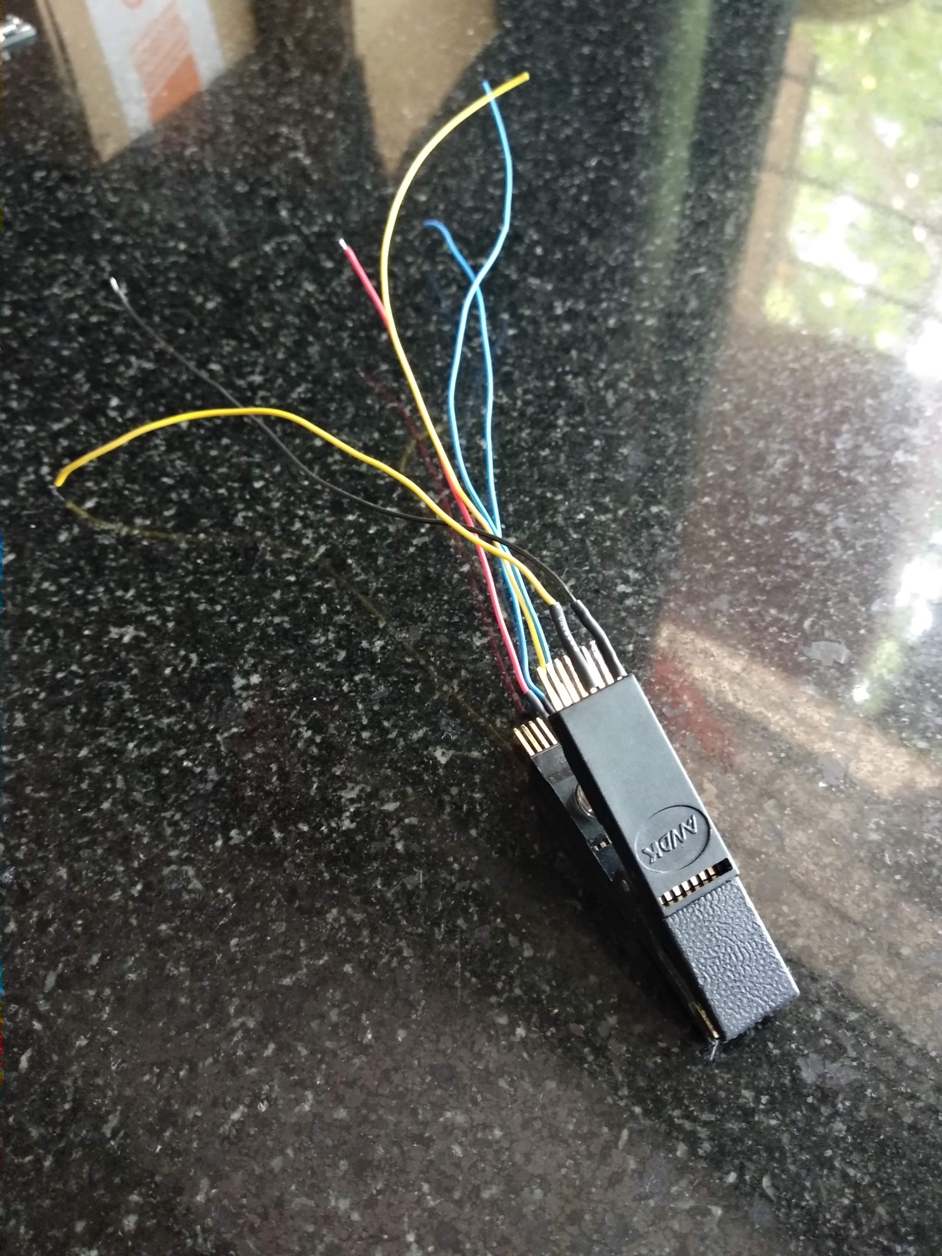
I got better and better information about the behavior of the system, which brought confidence to go ahead and attempt the Low Power code for the Attiny85.


 Matthias Rabault
 Joris Wegner
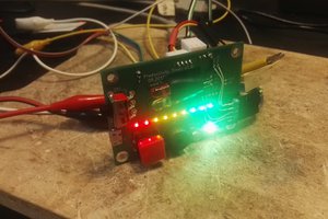
 Luke
Luke
 MobileWill
Glad to see this being worked on. I had a similar adventure in 2014 trying to fit it all inside the size of a pencil. ended up ditching all the electronics in favor of a bimetal switch to turn an LED on when it was above 145F.
A good battery suggestion is a CR435. used in fishing lures. very skinny.
If anyone cares to see the prototype: https://photos.app.goo.gl/Vop9jK6k81FQp7cH9