 Maave
MaaveThis was a slog. Lots of measuring with calipers and fiddling with Fusion. I did a lot of work that I had to refactor it into another body, got a couple graphical glitches in Fusion, struggled to import the PCB for reference, etc. But it's a little over half done now.
v1 case todo:
-cut a slot for the wires that connect each half
-make a top panel to hold the buttons in place.
-shape the start/select button slot
-hold the PCB into the case?
I've based this off my Nexus 6P case. The measurements haven't been adjusted for my Pixel 3 (not XL) yet. I'm going to leave it as-is for easy removal and so I can fudge the location of the phone. v1 is being designed with front access for easier debugging.

Here's the inside of the knockoff SNES controller that I based this on and took measurements from. v1 will use the D-pad and face buttons, two of the D-pad rubber (I have another) because they're narrower, the start/select rubber cut in half, and the shoulder buttons and rubber.

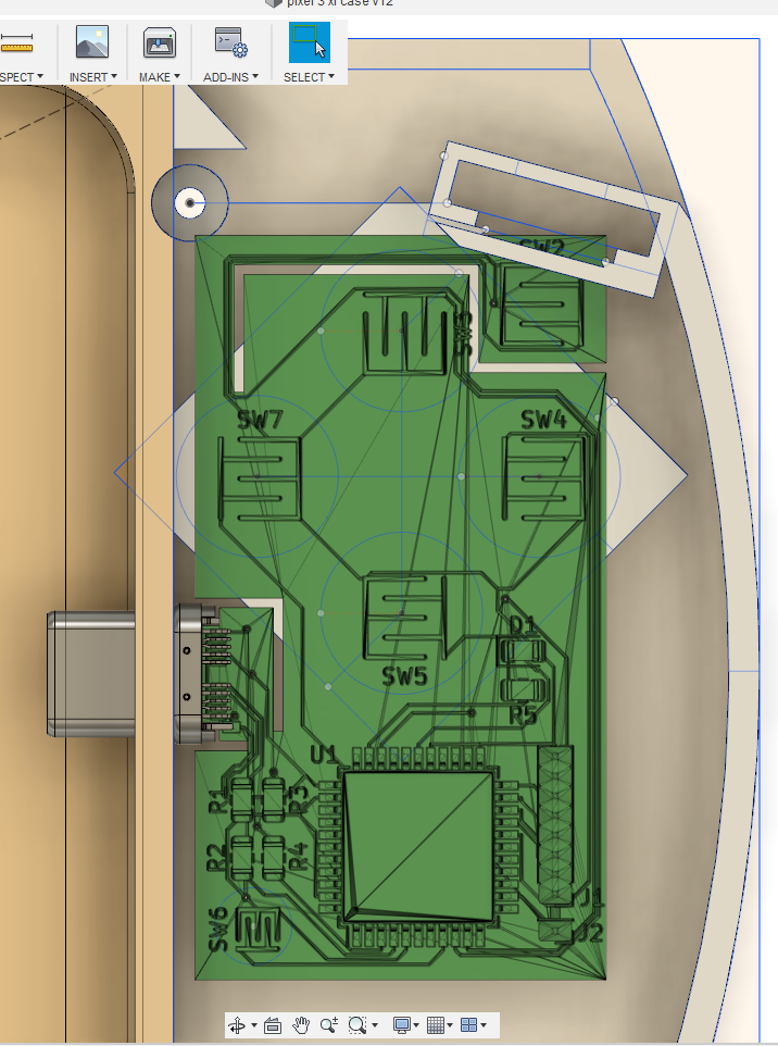
Here's where the PCB will sit in the case. There's actually a lot of ways I can play with the dimensions. The USB connector can move up or down, which will shift the entire PCB, with the width and distance from the phone can change, shoulder placement can change, etc. This will make a good testbed.
The shoulder button in the corner will bend and slide into a little slot inside the larger slot. I'll have to check the tolerances later to make sure the printer can make the thin tabs that will hold the shoulder button in place. The larger gap will hold the rubber dome. In the future I'll 3d print the shoulder button, maybe even with living hinge built into the case (inspired by the Fusion 360 hack chat).
The PCB has some changes. The shoulder button has moved to the other side. The USB-C connector edge cut has been tweaked (reading the docs helps lol) and now it looks more like the PD Buddy Wye that uses the same connector. I realized that it was incorrect when I loaded both models into Fusion and saw the connector clipping through the PCB. After changing the connector I shaved a tiny bit of width off the outer dimension. I tried to change the shoulder button cuts to a single cut (instead of an open slot) but pcbnew complained. Might do that again later.
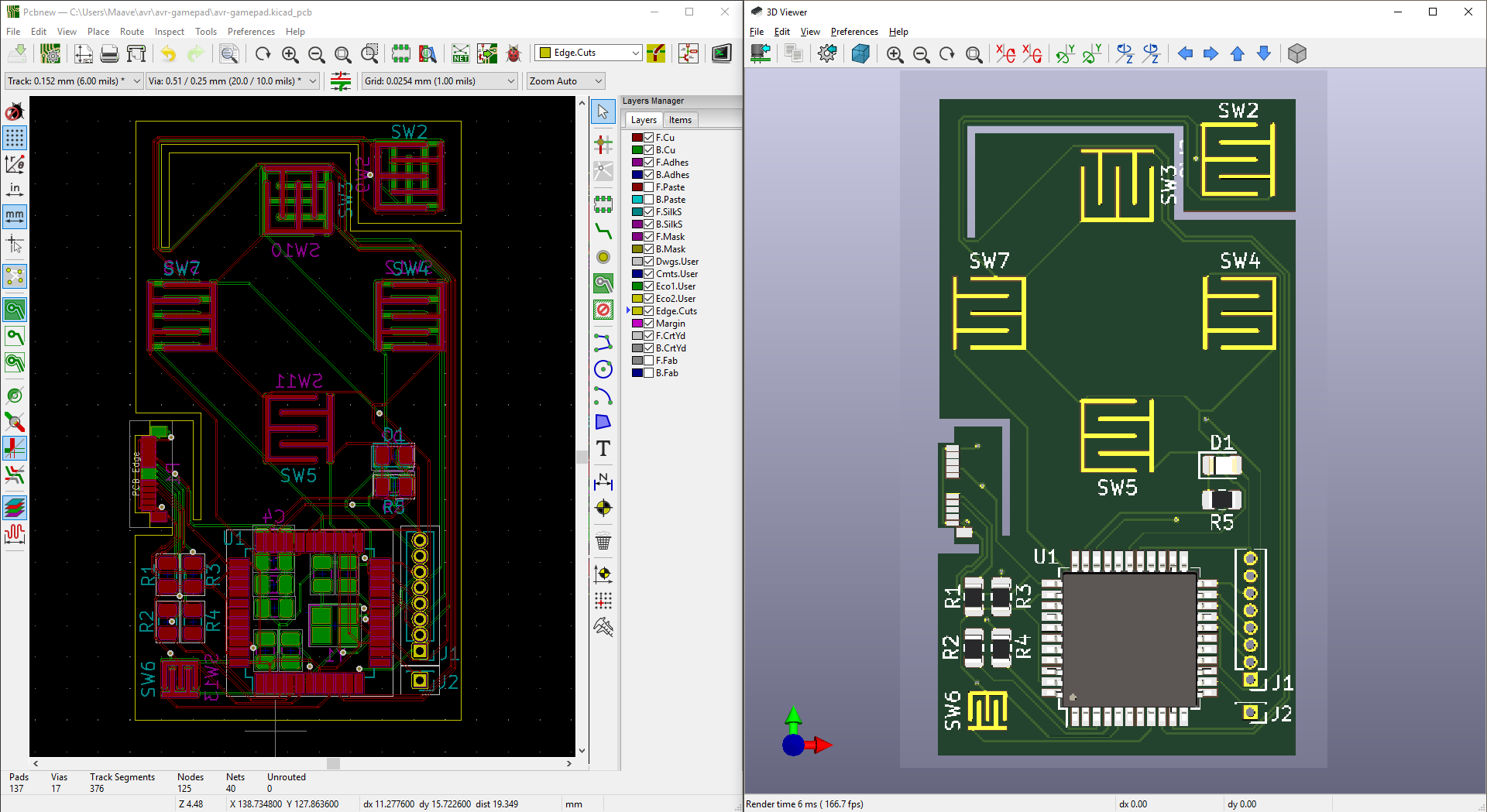
The process for getting the model into Fusion is dumb and I need to improve it. Export as VRML, import into Blender, export as STL, import into Fusion. That's the "simplest" way I could find that included all the traces and components. I need to either get 1-click exporting or script it.
I have some ideas for future versions. Like a rigid PCB for the main portion and a strip of flex that acts as triggers and connects both sides. Switching to rigid would reduce cost, fit the USB connector better, and give me a colorful solder mask. I have some sick PCB art planned that uses OSHpark's purple and gold or PCBway's red and gold. The art will remain a surprise until I can pull it off.
Onward!
Discussions
Become a Hackaday.io Member
Create an account to leave a comment. Already have an account? Log In.