 Tyler Gerritsen
What's New?
The design for Edgerton has been updated to address several issues in the original design. The circuit diagram, bill of materials, and 3D print files have been updated. A new complete assembly manual has been written and made available. The overall cost has increases slightly (less than $5) because of some new components. Assembly requires a few more steps, but they are simple and the benefits greatly outweigh the cost and added assembly time. Below is a brief overview of the changes and their rationale.
Reduced Power Consumption
The microcontroller's isolation from the high-voltage boost converter is important to prevent resetting, and this was originally accomplished using a relay board purchased from eBay. Unfortunately the relay drew several hundred milliamps, about as much as the boost regulator.
The relay has been replaced with a P-channel MOSFET, opto-isolator, and a couple resistors. The new circuit draws about 30 mA - and may be reduced further with some optimization. Isolation is maintained via the opto-isolator. The cost has not increased and the circuit is easy to assembly and install. A small benefit is the removal of the relay mount in the case, which means a reduction in filament usage.
Ferrite Beads for the Gates
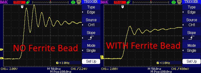
I previously noticed some significant ringing in the MOSFET gates. Thanks to advice from a friendly German named Volker and guidelines presented in this application note from ON Semiconductor, I ordered some ferrite beads and installed them at the MOSFET gate leads. Here's the gate signals before and after the ferrite beads were installed.
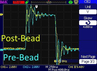
The gate signal is cleaner. Here's a trace showing how much the ferrite bead cleans up the signal.
LED Series Resistors
Typically LED's are never connected directly to a power source. Series resistors or drivers are used to regulate power consumption. The original design for Edgerton did not include any components to limit current to the LED to maximize efficiency. Unfortunately the LED voltage showed a concerning amount of ringing during switch-on and switch-off.
The 1.1 revision now includes 2-ohm series resistors on the LED anodes. Metal film resistors were selected to minimize inductance. Although the resistors dissipate far more than the 1/4 W they are rated for (it's actually more than 300 watts), the power lasts for such a short amount of time that it's not problematic.
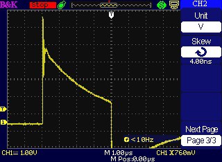
Below is a trace of the voltage across the resistor with a 95V driver voltage. NOTE that this was tested after the ferrite beads were installed. The turn-on current is very smooth, but there's still ringing during turn-off. That's may be due to inductance in the circuit. The decrease in current is interesting and I will have to investigate it further to be sure it's not caused by heating of the resistor.
Previously, the LED current could only be calculated by measuring the capacitor voltage before and after a pulse, and multiplying the voltage drop by the capacitance and duration. Now the current can be directly measured using the series resistor. Every volt dropped is two amps of current, so the trace above shows a maximum current of about 13 amps.
A quick-ref table shows that 5-guage stranded wire is recommended for such current. This made me giggle just a little...
The recommended LED drive voltage needs to be re-evaluated. Currently I'm running at 120 V, of which only 90 V reaches the LED's.
Gate Driver High-Pass Filter
During initial development of the control circuitry, I was concerned about the possibility of driving the LED's for greater than 4 microseconds. I researched the topic and asked for advice on a popular forum, but it seemed the only solution was using a 555 circuit - which I wasn't keen to use as it would be difficult to tune and complicated to adjust the pulse length.
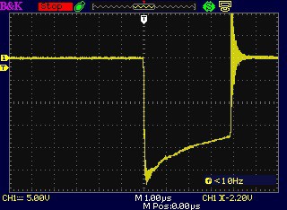
My fears were confirmed when I recently destroyed all twelve LED's during an ill-designed experiment. This led to further research and the discovery of an incredibly simple high-pass filter circuit - it's just a low-pass RC circuit, but with the resistor and capacitor swapped! Using a 100 nF ceramic capacitor and 1.5k ohm resistor, the circuit prevents the TC4452 drivers from activating longer than about 5 microseconds. Here's the driver's input signal:
The TC4452's datasheet indicates the input 'OFF' voltage to be 0.8 - 1.3 volts. Also, the minimum input voltage is -5 volts, so the signal inversion isn't a problem. As shown in the series resistor voltage shown above, the gate is not turning off before a 4-microsecond pulse is complete.
External Trigger Protection
The original external trigger line was connected directly to the microcontroller's input pin. This is poor practice and would more than likely lead to a damaged microcontroller (or worse, activation and destruction of the LED's). Research into the topic of protecting the external input without affecting the signal response has led to the current design.
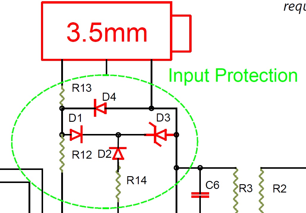
Several diodes are required, but fortunately the cost is not increased significantly. I have yet to actually test the new design for any delays introduced and its ability to protect the controller. As such, the design may be updated in a future revision.
Piezo Buzzer
Previously, in order to ready the flash, the user was required to press the button and watch the display until the flash was charged. The board is now equipped with a piezo buzzer. This simple addition gives an audible confirmation of the unit's readiness during use. Four fast beeps indicates to the user that the flash is ready, so the user is not required to stare at the display to confirm it successfully entered the ready state.
The buzzer is optional, and the firmware will include a switch to disable the pin. If the buzzer is not used, the pin should be tied to ground.
Discussions
Become a Hackaday.io Member
Create an account to leave a comment. Already have an account? Log In.