 SCART VADER
Disclaimer: Use the information provided here at your own risk. I do not take any responsibility for any resulting damage.
This adapter is based in the cheap PIC16F18313 microcontroller following Visenri's indications. It has the following pros:
- It automatically detects the polarity of the input VGA sync signals and configures the configurable logic cells (CLC) of the PIC dynamically to generate the SCART composite sync signal correctly.
- If the frequency of the VGA horizontal sync signal is wrong or if the VGA vertical sync signal does not change then the PIC disables the SCART composite sync signal, the SCART RGB selection signal and the SCART status signal.
- Most VGA devices can provide enough power to the PIC so no external power source is required.
- No external power source nor DC-DC converter is required to generate the 12V of the SCART status signal. It can be generated by the PIC itself as noted by Visenri.
- Optional aspect ratio selection.
- Optional LEDs to test the power and input sync signals.
- Optional power source selection.
- The basic circuit only requires the PIC and a pair of resistors and capacitors.
- The full circuit fits in a (big) DE-15 enclosure using a single sided PCB and easy to solder through-hole components.
1 Pin outs
PIN # |
name | description |
|---|---|---|
| 1 | RED | Red video |
| 2 | GREEN | Green video |
| 3 | BLUE | Blue video |
| 4 | ID2/RES | formerly Monitor ID bit 2, reserved since E-DDC |
| 5 | GND | Horizontal sync ground |
| 6 | RED_RTN | Red return |
| 7 | GREEN_RTN | Green return |
| 8 | BLUE_RTN | Blue return |
| 9 | KEY/PWR | formerly key, now +5V DC, powers EDID EEPROM chip on some monitors |
| 10 | GND | Vertical sync ground |
| 11 | ID0/RES | formerly Monitor ID bit 0, reserved since E-DDC |
| 12 | ID1/SDA | formerly Monitor ID bit 1, I²C data since DDC2 |
| 13 | HSync | Horizontal sync |
| 14 | VSync | Vertical sync |
| 15 | ID3/SCL | formerly Monitor ID bit 3, I²C clock since DDC2 |
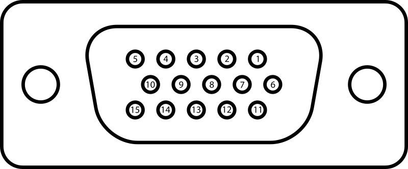
Table 1: Pin out of a female DE-15 connector functioning as a VGA output from wikipedia
PIN # |
description |
|---|---|
| 1 | Audio output (right) |
| 2 | Audio input (right) |
| 3 | Audio output (left/mono) |
| 4 | Audio ground |
| 5 | Blue ground |
| 6 | Audio input (left/mono) |
| 7 | Blue |
| 8 |
Status & Aspect Ratio 0–2 V → off +5–8 V → on/16:9 +9.5–12 V → on/4:3 |
| 9 | Green ground |
| 10 | not used in this project |
| 11 | RGB Green |
| 12 | not used in this project |
| 13 | Red ground |
| 14 | pin 8 ground |
| 15 | Red |
| 16 |
RGB selection 0–0.4 V → composite 1–3 V → RGB |
| 17 | Composite sync ground |
| 18 | pin 16 ground |
| 19 | Composite sync output |
| 20 | Composite sync input |
| 21 | Shell/Chassis |
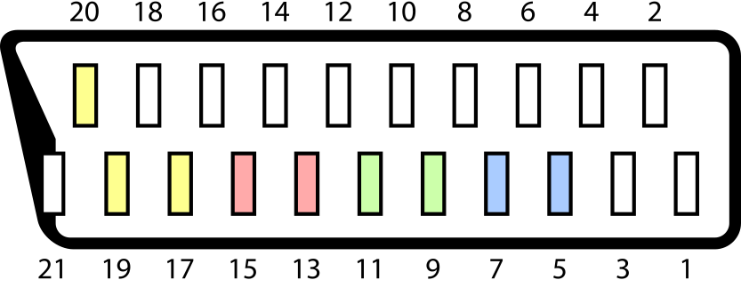
Table 2: Pin out of a SCART connector from wikipedia
2 Connections
2.1 Common ground
The HSync ground (VGA pin 5), VSync ground (VGA pin 10), ID0/RES (VGA pin 11), status ground (SCART pin 14), composite ground (SCART pin 17), RGB selection ground (SCART pin 18) as well as the ground of the PIC and the external power sources (if used) must be wired together.
2.2 Power source
In this project, the PIC requires a power source of 5V. If the device generating the VGA signal is not very old, it will probably provide 5V through the pin 9 of the DE-15 connector. If it complies with the DDC host system standard then it will supply at least 300 mA, which is enough to power the whole circuit. So, you can probably connect the Vdd pin of the PIC to the VGA pin 9 and you will not need an external power source. Just in case, I included a switch and a mini-USB socket in the circuit so the power source is selectable. If the switch is in the left position, the PIC is powered by the VGA pin 9. Otherwise, it is powered by a external power source through the mini-USB connector. It is advisable to connect decoupling capacitors between the supply pins of the PIC to ensure it works properly. The manufacturer recommends two capacitors of 0.1μF and 0.01μF in parallel.
2.3 RGB signals
You must connect the VGA red (VGA pin 1) to the SCART red (SCART pin 15), the VGA green (VGA pin 2) to the SCART green (SCART pin 11), the VGA blue (VGA pin 3) to the SCART blue (SCART pin 7), the VGA red return (VGA pin 6) to the SCART Red ground (SCART pin 13), the VGA green return (VGA pin 7) to the SCART green ground (SCART pin 9) and the VGA blue return (VGA pin 8) to the SCART blue ground (SCART pin 5).
2.4 Sound signals
You must connect the analog audio groud of your system to the SCART audio ground (pin 4). The left and right audio signals of your system must be connected to the SCART left and right audio inputs respectively. These are the pins 6 and 2 of the TV SCART connector respectively. However, if you are making your adapter using a female SCART connector and a standard SCART cable you must take into account that it has some wires crossed. In that case you must connect the left and right audio signals of your system to the left and right audio outputs of the female SCART connector of your adapter (pins 3 and 1) respectively.
2.5 Sync signals
When a field is being drawn, the SCART composite sync signal is normally 0.3V, and there are pulses to 0V during the horizontal blanking intervals. The polarity of the pulses are inverted during the vertical blanking intervals. This composite sync signal is generated by the PIC from the horizontal sync signal (VGA pin 13) and the vertical sync signal (VGA pin 14) making the following connections:
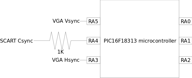
The PIC automatically detects the polarity of the horizontal and vertical sync signals and configure the CLC so the SCART composite sync signal is the EXOR of both if they have different polarity or the NEXOR of both otherwise. Also, The PIC will set the composite sync signal to ground if the frequency of the input sync signals is wrong to protect your monitor. The composite sync signal is the pin 20 of the TV SCART connector, and has an impedance of 75Ω. The 1KΩ resistance is necessary to reduce the H level of the composite sync signal to 0.3V approximately. Again, if you are making your adapter using a female SCART connector and a standard SCART cable you must take into account that it has some wires crossed. In that case you must connect the generated composite sync signal to the sync output of the female SCART connector of your adapter (pin 19).
2.6 RGB selection
The voltage of the SCART pin 16 (RGB selection) must be between 1V and 3V to select the RGB mode. This pin has an impedance of 75Ω. The RGB selection can be generated by the PIC adding the following connections:
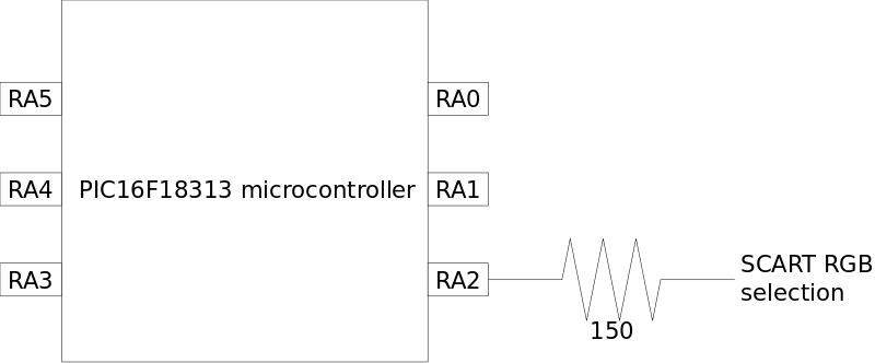
The 150Ω resistance is necessary to reduce the H level of the RGB selection signal to 1.7V approximately. The PIC will set this signal to ground if the frequency of the input sync signals is wrong.
2.7 Status & Aspect Ratio
You can leave the SCART pin 8 (status/aspect ratio) unconnected, but you will have to select the SCART input of your TV manually. If you want the TV to switch to the SCART input automatically, pin 8 voltage must between 9.5V, and 12V (or between 5V and 8V to indicate an aspect ratio of 16:9 in some TVs). As noted by Visenri, such a voltage can be generated by the PIC using a Dickson circuit as shown bellow:
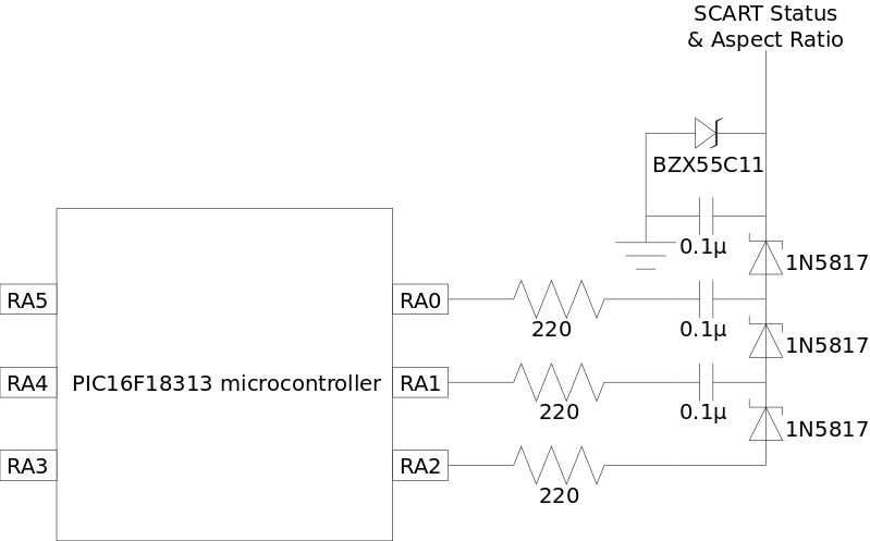
The capacitors should have a breakdown voltage greater than 15V. The 1N5817 are Schottky diodes. Any Schottky diode able to handle a forward current of 30mA should be OK. The BZX55C11 is a Zener diode with a breakdown voltage of 11V. I included it because I thought a voltage level above the nominal values could damage my TV. You can remove it if you are brave enough. Otherwise you can use any Zener diode able to handle a reverse current of 30mA with a breakdown voltage between 10V and 12V. In my case, I wanted to be able to select the aspect ratio between 4:3 and 16:9 so I replaced the BZX55C11 by two BZX79-C5V6 and a switch in this way:

The BZX79-C5V6 is a Zener diode with a breakdown voltage of 5.6V. You can replace it with any Zener diode with a breakdown voltage between 5.5V and 6V as long as it is able to handle a reverse current of 30mA. Again, the PIC will disable the status signal if the frequency of the input sync signals is wrong.
2.8 Test LEDs
You can test the power source and the frequency of the input sync signals adding the following connections:

The value of the resistors depends on the type of LEDs you are using. If the resistance is too low, the LEDs can be damaged. Also, it must be taken into account that the maximum current rating of the RA2 pin is 50mA. I used resistors of 680Ω. The LEDs will provide test information according to the following table:
| green LED | red LED | meaning |
|---|---|---|
| off | off | The circuit is not powered. |
| off | on | The power source is too weak or the frequency of at least one of the input sync signals is wrong. |
| on | off | The circuit is powered and the frequency of the input sync signals are OK. |
3 Microcontroller firmware
The compiled firmware can be downloaded here. The C source code can be downloaded here.
4 My implementation
4.1 Bill of materials
4.2 printed circuit board
The PCB I used is shown bellow. The holes for the SCART wires are labeled E2,..,E21. Note that you don't have to connect all the SCART wires. You can download the GERBER files here and the KiCad project files here.
