 Tim Wilkinson
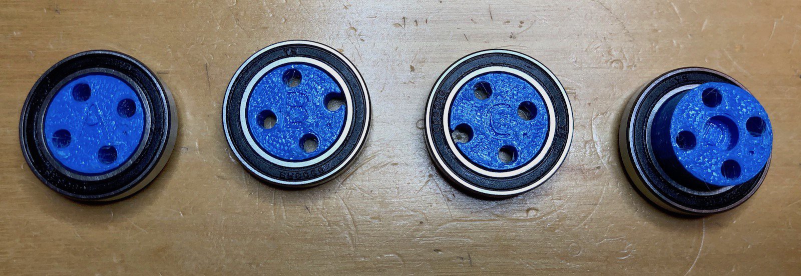
Next push the B and C pieces into the two cycloidal disks. It doesn't matter which way round these are mounted or which disk goes on which bearing. Push them on until they are flush with the bearing.

Now push the A and D bearings into the two "keyhole" shaped pieces. These pieces are identical. The A bearing should have the letter pointing "in" so you can see the holes in the piece, the D bearing should be pointing out.
Push the four M3 40mm screws though the center holes of the "A" bearing.
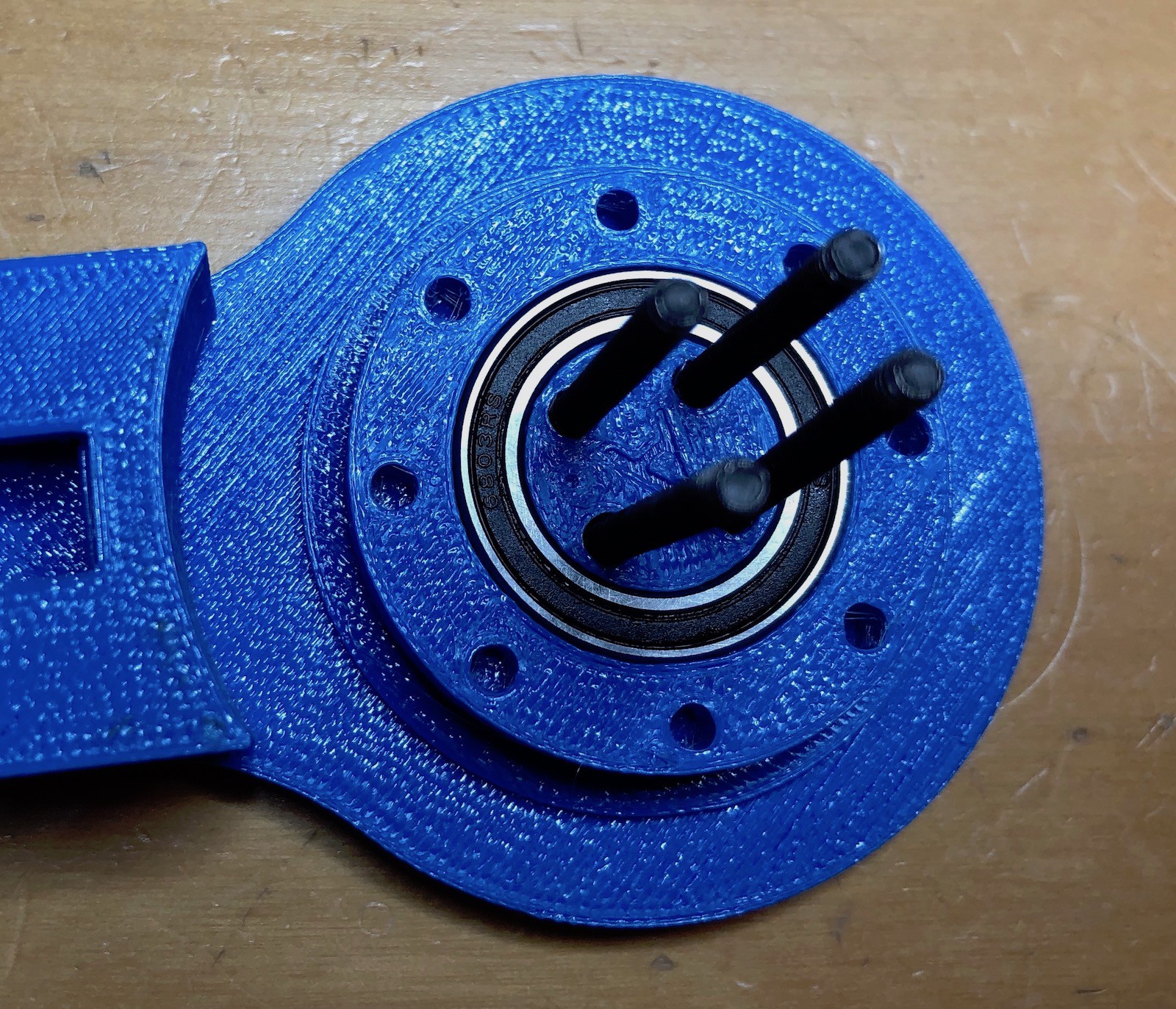
Add the larger bearing.
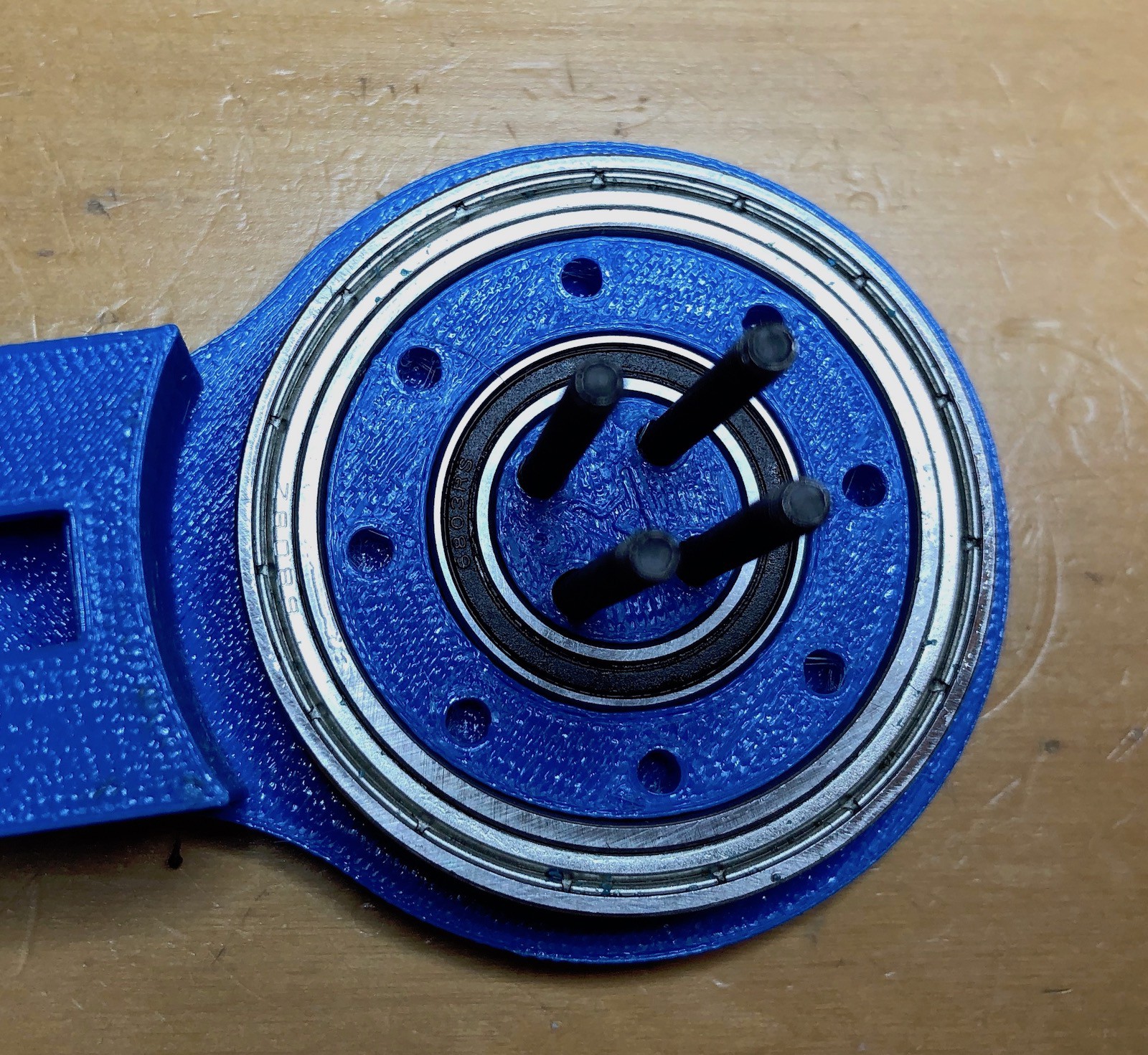
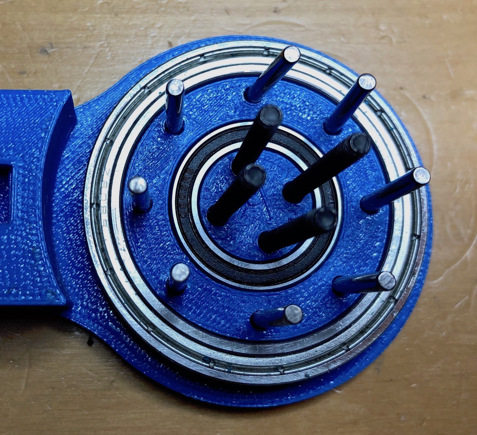
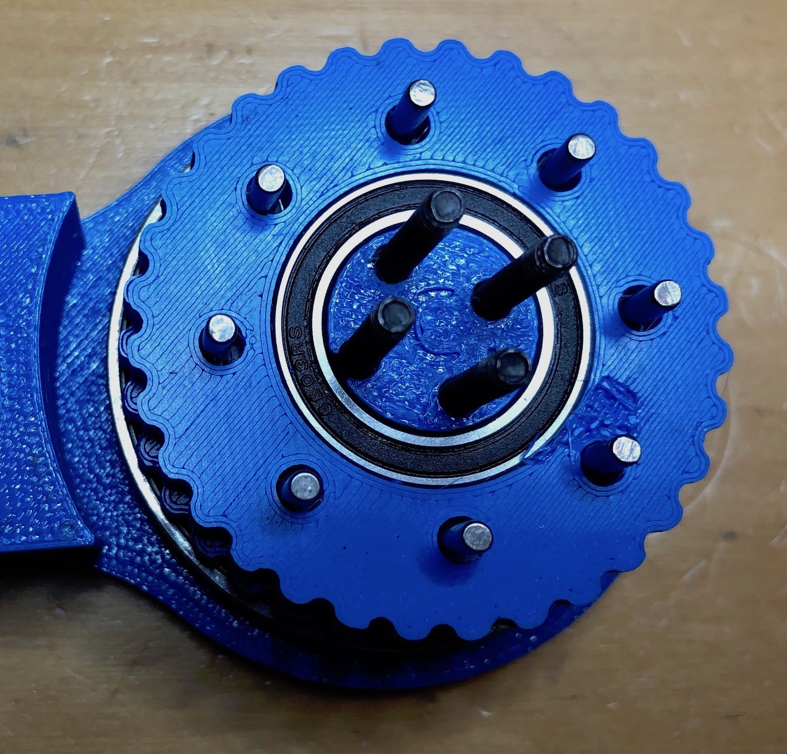
And insert the 8 pins into the holes. These should be relatively loose fitting.
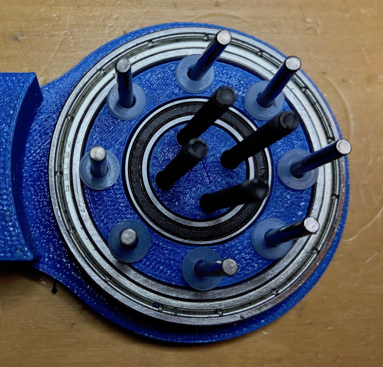
On each of the pins, add a nylon washer. These washer will keep the final assembled parts parallel. While everything has a tight fit, 3d printed pieces will move when the joint is in use and these washers keep everything "true". Without them the joint tends to lock up over time.
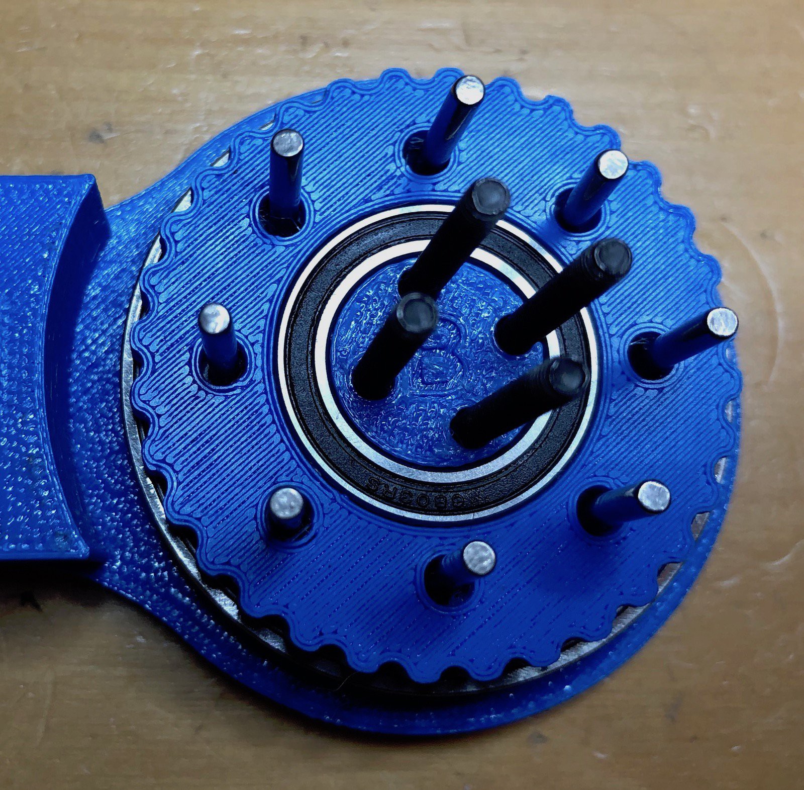
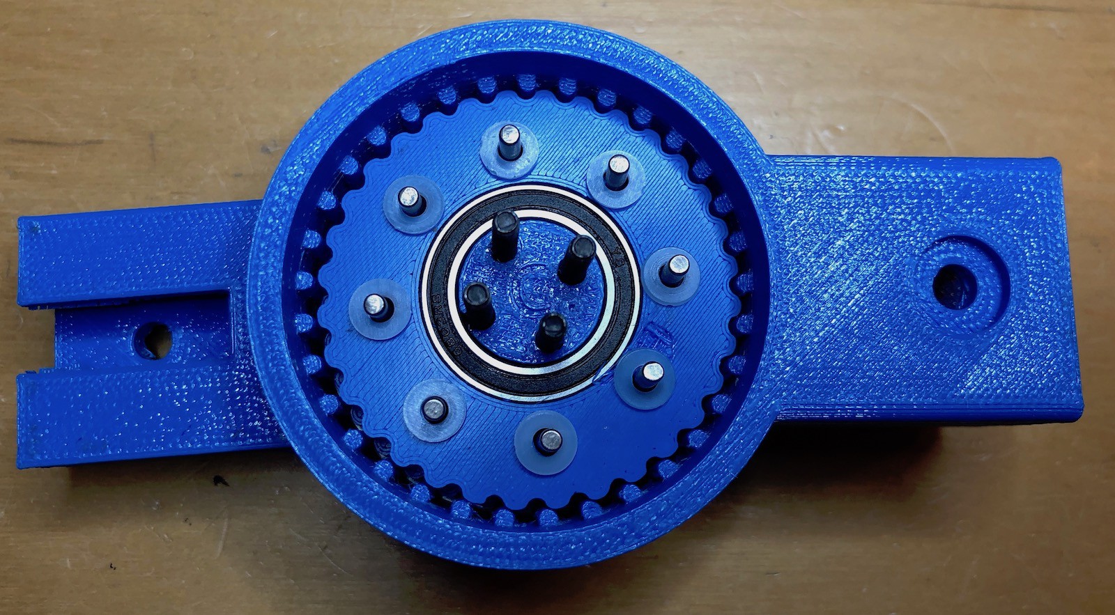
Now insert the "B" part over the screws and pins. How these are lined up is important as you'll notice the holes in the A, B, C and D pieces are not all the same. Each pieces should be assembled so the A, B, C and D as all the same way up. There is also a small dot on the bottom/right of each letter. These should also line up.
Add 8 more washers.
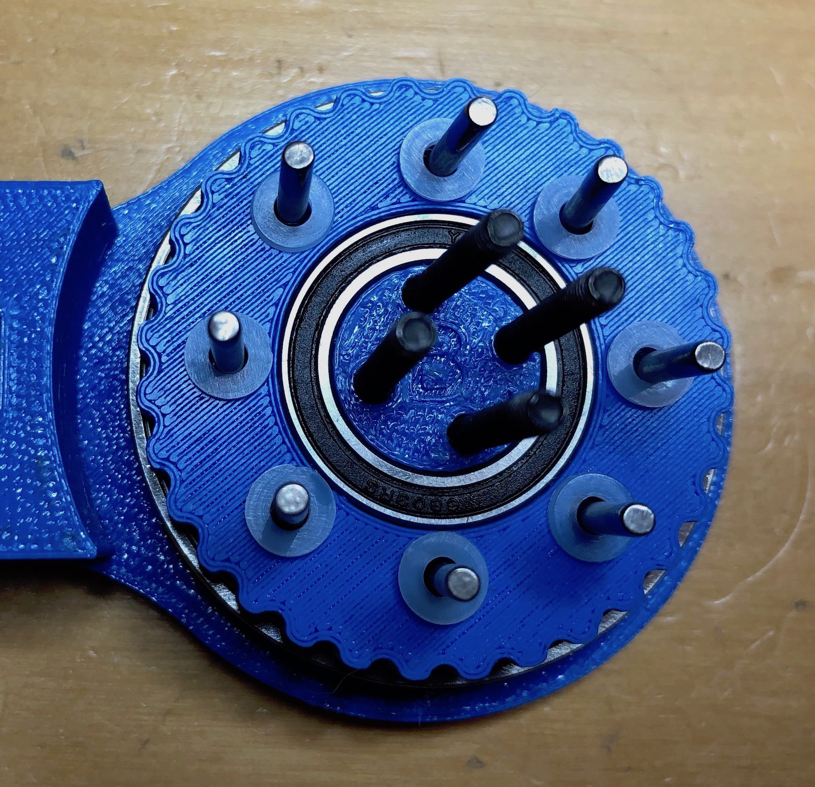
And then part C, remembering to line up the letter and the dot.
Add then the final 8 nylon washers.

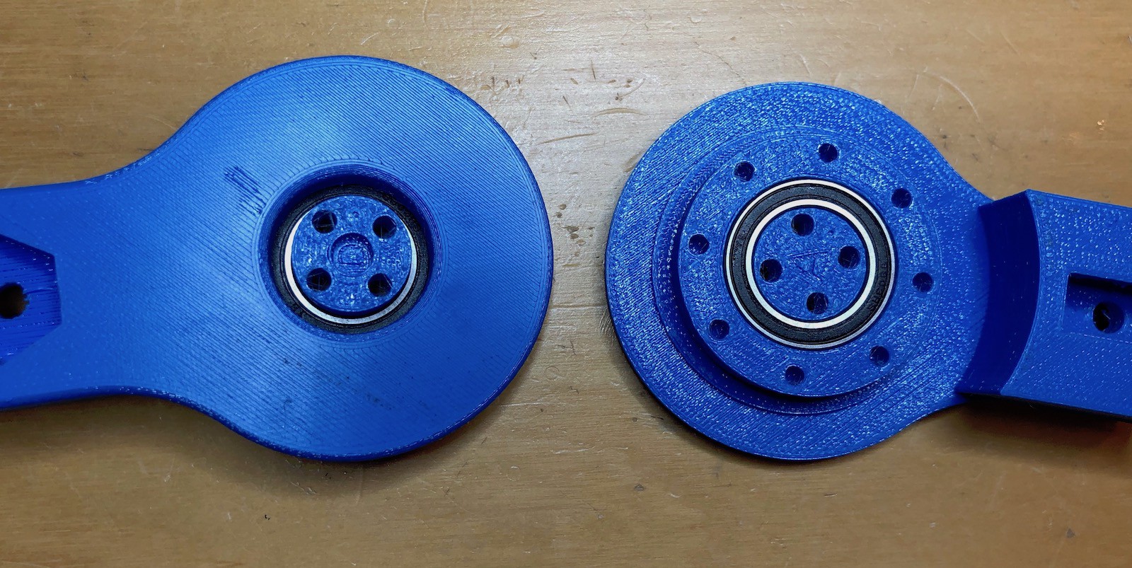
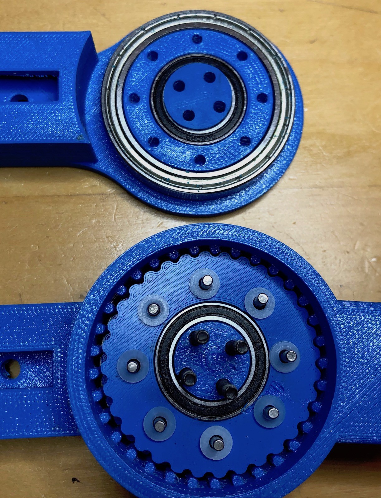
Now carefully place the "output" shaft (that's the circular collar part) around the cycloidal disks. You may need to wiggle it into place. It doesn't matter which way up it goes, and the exact position is unimportant.
Prepare part "D" by adding the remaining (large) bearing.
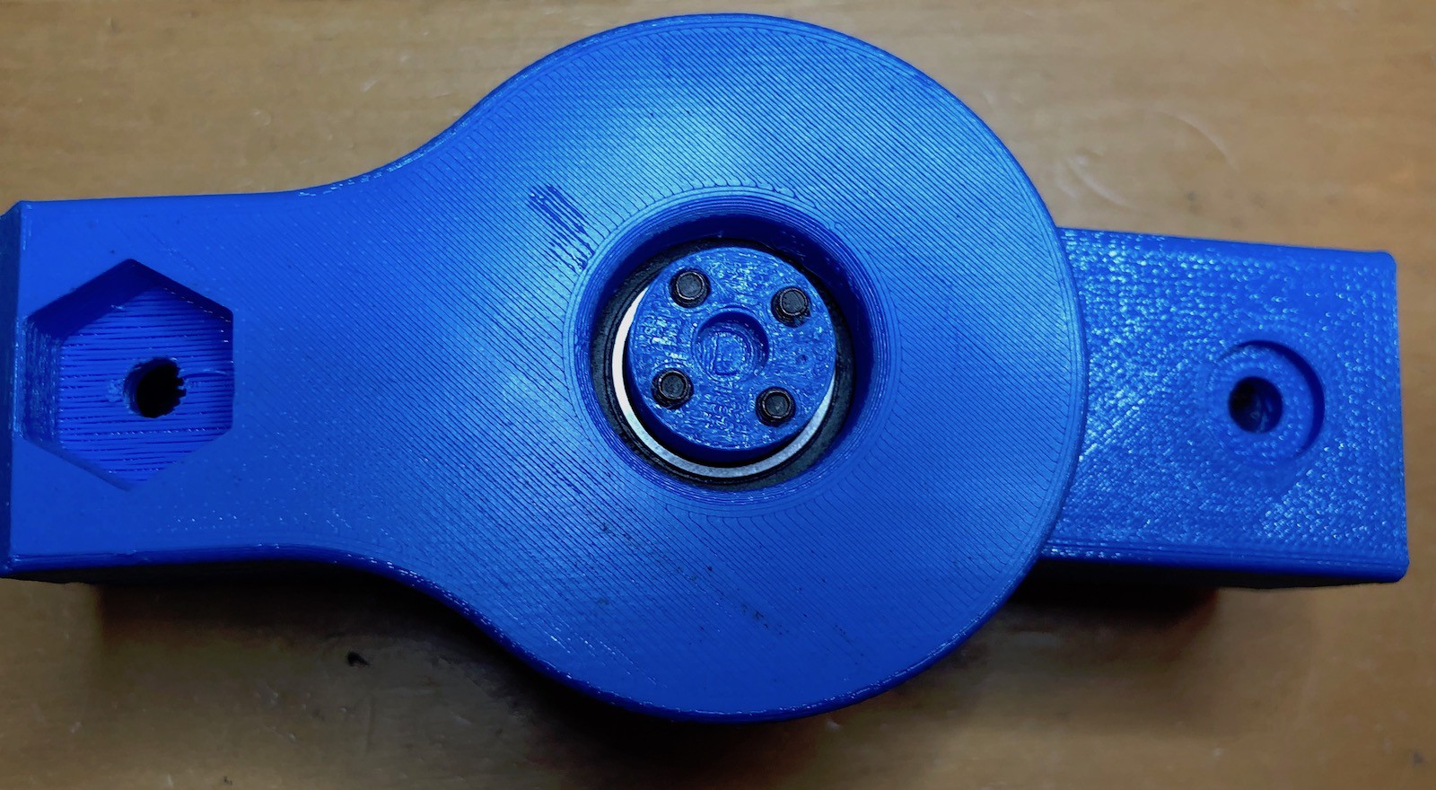
Then push it carefully onto the parts already assembled, again lining up the letter and the dot. This can take a bit of jiggling because you need to get all the pins and screws into their respective holes. Once you're done it will look like this.
Now we need to attach the motor. The 40mm screws are spaced to attach directly to the motor.
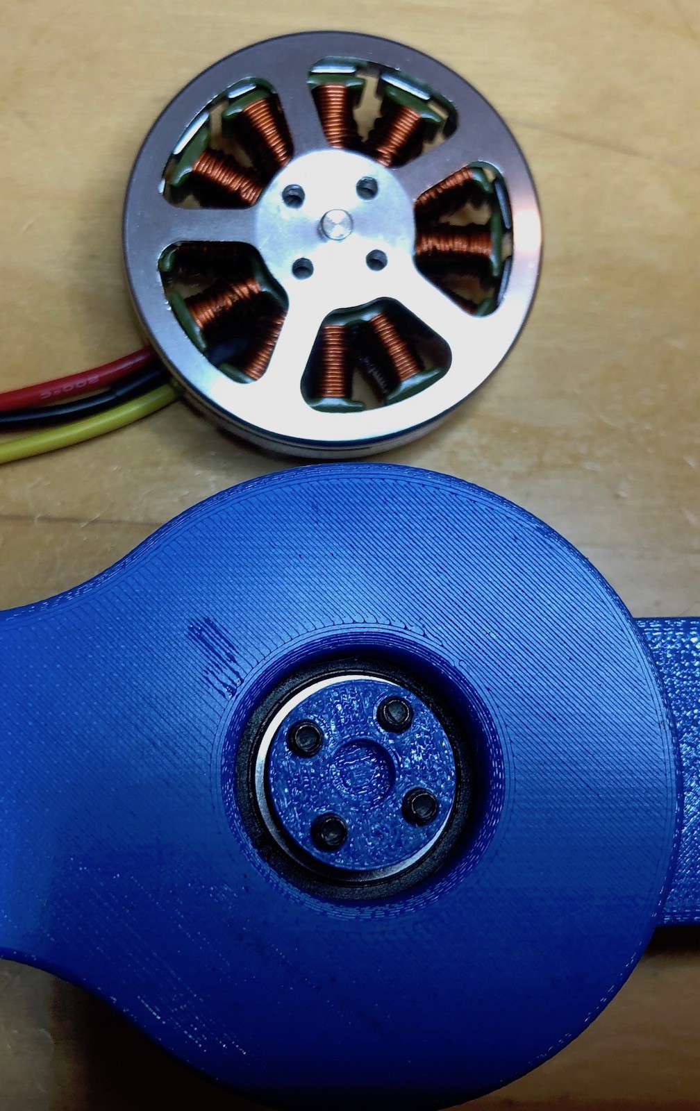
Carefully place the motor on top of the assembled joint such that the screws line up with the holes in the motor.
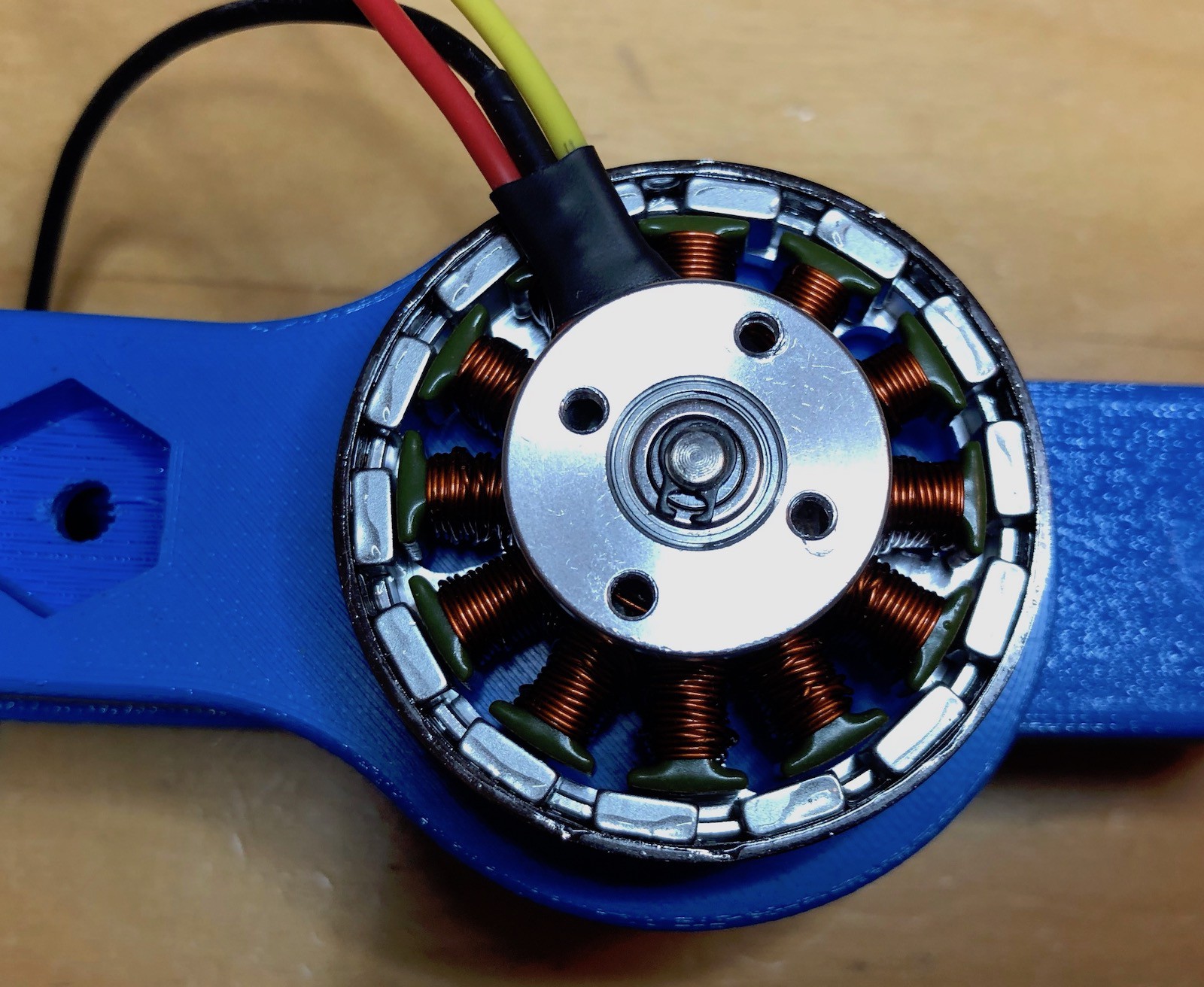
Screw the screws into the motor to secure everything. This can be fiddly and I sometimes have to rotate the motor body back and forth a bit as I "feel" where the screws go.
There's one final piece to add; to secure the motor to the rest of the joint. Push the motor mount into the hexagonal hole and rotate the base of the motor until it lines up with the holes on the motor mount. On these motors, the holes are not all at the same distance from the center.
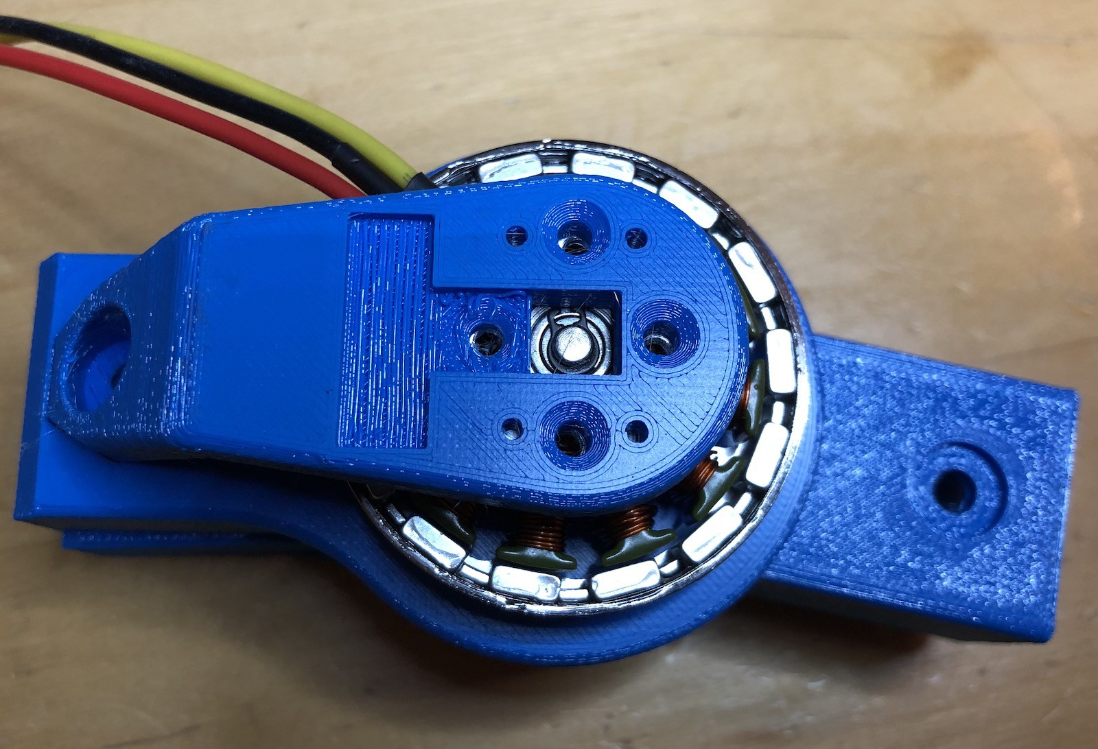
Use the 4 small screws to attach the motor to the mount. One of these screws is shorter than the others and should be used in the "cut-out" on the mount. This cut-out is for mounting the rotational encoder (which I'll describe separately). You can probably get away without that short screw if you want.
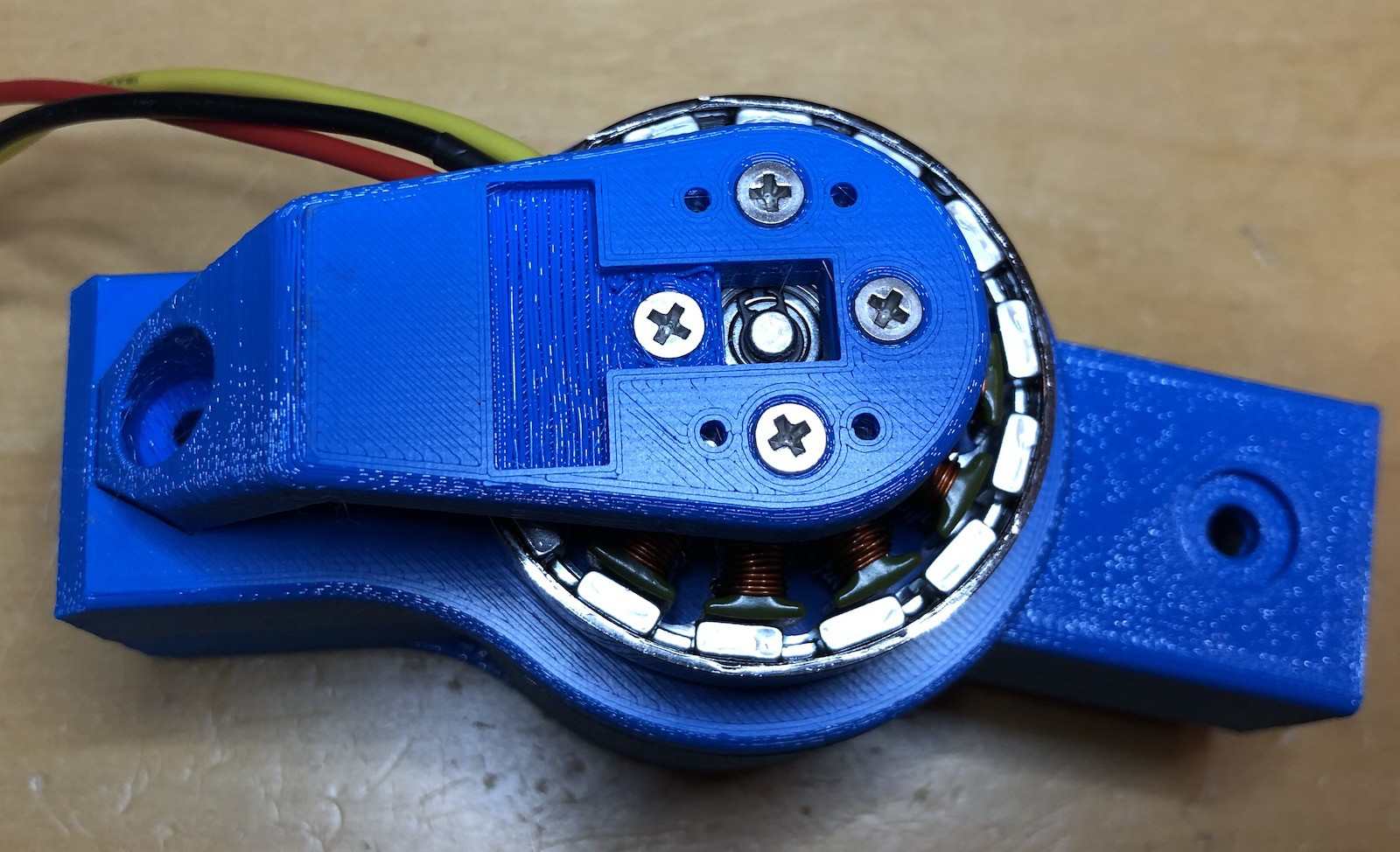
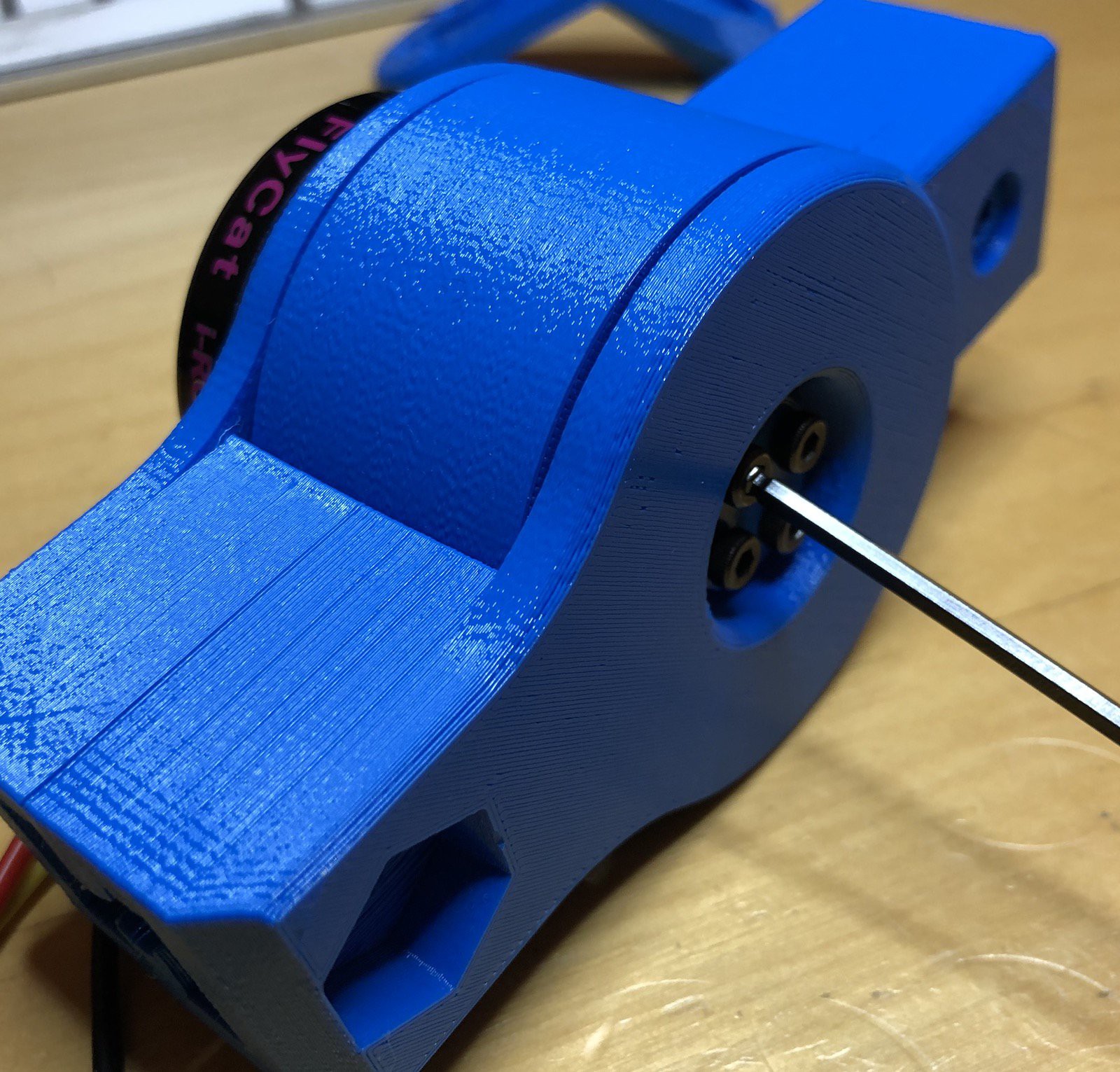
And there we go.
The joint itself mounts onto 2020 aluminum extrusion.
If all has gone well, if you rotate the motor by hand the joint should move. You should also be able to rotate the joint by hand and make the motor spin.
Discussions
Become a Hackaday.io Member
Create an account to leave a comment. Already have an account? Log In.
Hi Paul,
Adding a bushing to these pins is a good thought - I'll have to see if I can find something appropriate to use. I did think about adding a nylon bushing at one point (some bits of PTFE tubing) but never followed through as I need to make changes to make that fit. I also have some watch pins to try out, but I suspect they won't be strong enough. But I'll give them a go at some point.
Are you sure? yes | no
Hi Tim,
It is looking really good. Using the 4 bolts is a very clever idea. The inner 8 pins take a lot of force and have a lot of friction, especially under load. Have you thought about bronze bushings or something similar?
Paul
Are you sure? yes | no