 Reed Foster
Frequency-modulated continuous wave radar is a technique of interferometry for measuring distance (and speed with some post-processing) of objects by transmitting a frequency modulated signal and measuring the difference in frequency between the delayed receive signal and the (currently transmitted) reference signal. When two signals close in frequency interfere, they produce a beat tone. The frequency difference between transmitted and received EM waves is measured by interfering the waves and measuring the envelope of the beat tone they create.
The architecture of an FMCW radar is shown below:
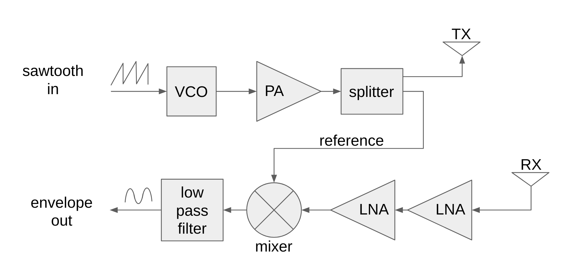
The main focus of this project was the design and implementation of the power splitter and mixer circuits.
The splitter is a coupled-microstrip directional coupler. When a voltage (and current) travels down a PCB microstrip, there is a corresponding electric field (and magnetic field) between the microstrip and the groundplane on the opposite side of the dielectric substrate. In the center of the microstrip, the electric field is uniform, but towards the edge of the microstrip it fans outwards, spilling over the boundary of the copper microstrip. This has the (potentially undesirable effect) of allowing two microstrips that are physically close together to couple power through fringing electric fields. In the case of power couplers and splitters, this is quite advantageous, and by adjusting the separation between the two strips, the amount of power that is coupled between the strips can be adjusted to a desirable value.
For the purposes of our project, we wanted very weak coupling between our microstrips because whatever power that is coupled is not transmitted, and since the power is coupled after the transmit amplifier, we wanted to maximize the power transmitted. This meant we had a relatively large separation between the two coupled microstrips.
Using Qucs (Quite Universal Circuit Simulator), we determined dimensions for the microstrip coupler and attached traces (some of which were impedance transformers to match our 50Ω design) which provided optimal scattering parameters for our purposes shown below:
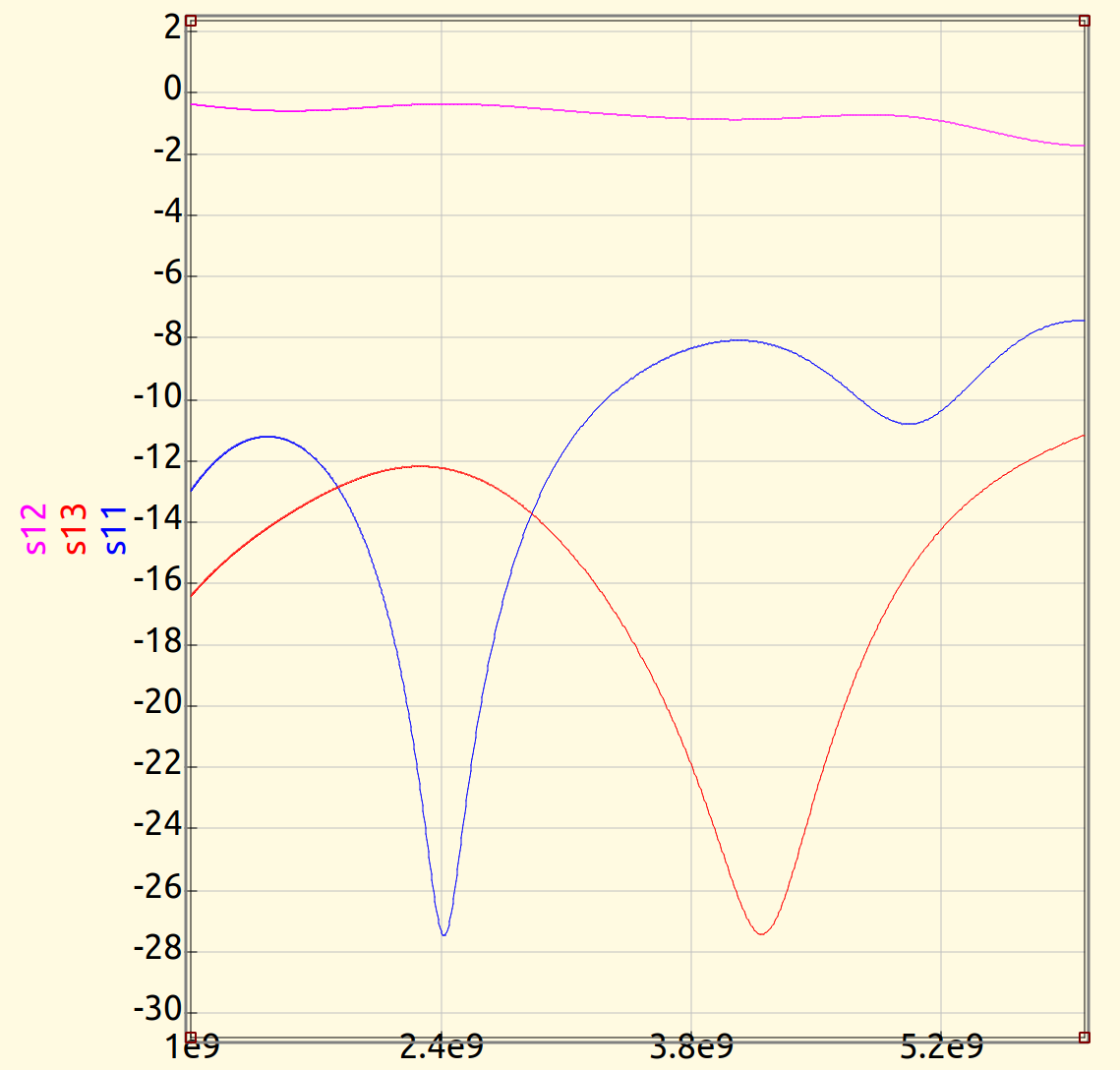
The vertical axis is magnitude in dB and the horizontal axis is frequency in Hz. The blue curve (S11) is power reflected by the coupler, which we see is minimized around the center frequency of our radar design (which is desirable). The red curve (S13) is the power coupled through the coupler. -12dB coupled corresponds to about 6% of power coupled. Nearly all power is transmitted as is shown by the pink curve (S12).
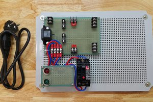
We milled a prototype on FR-1 substrate and measured its scattering parameters with a network analyzer. The prototype is shown below with one of its terminations disconnected — the termination was connected for testing (the burn marks were from heating up the board in an attempt to weaken the double-stick adhesive used to stick the board to the mill):
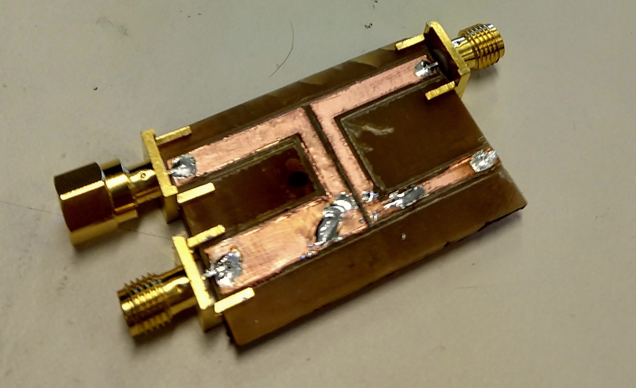
Unfortunately, the prototype we built was not perfectly centered at 2.4GHz and had a high reflection coefficient (-10dB), however it had decent power coupling (-17dB) and transmission (-7dB). Some of this loss (and reflection) we attributed to poor connection between our SMA connectors and the PCB.
The mixer circuit consists of a summing mixer and a half-wave rectifier RC circuit to detect the envelope of the sum. The summing mixer is a Wilkinson power combiner which has the nice property of port isolation; the two input ports (on the right of the picture) are separated by a half-wavelength through the combiner and through the (ideally) zero length resistor, any power through one input port will destructively interfere with itself at the other output port.
Our prototype pictured below (which we milled out of FR-1; somehow it turned out far more aesthetically...
Read more »
 Victor Joo
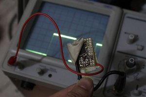
 Yann Guidon / YGDES
 Nguyen Vincent
 Mario Ninic
Good job. I'm in my third year and I'm interested in this field. Next year I will do my graduation thesis on radar. Would you mind sending me your files (including your schematic file) so that I can know more about this field? Because this field is new to me, I hope you can send me all your files relating to your progress so that I could have a deep understanding about this area. I promise if I use any ideas in your report, I will ask for your agreement. Thank you very much and hope you have a nice day. Here is my email: ntrongden13@gmail.com