0%
0%
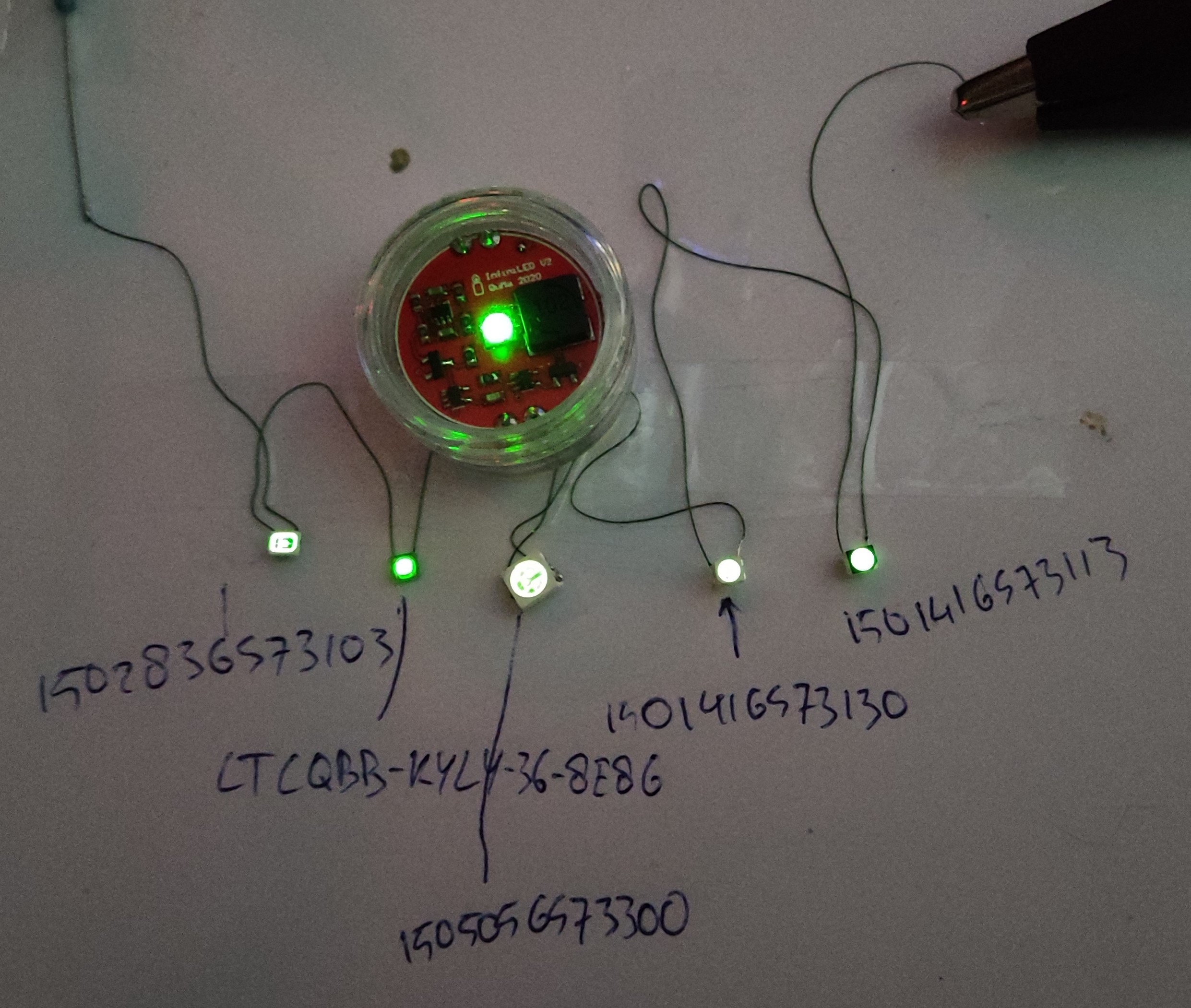
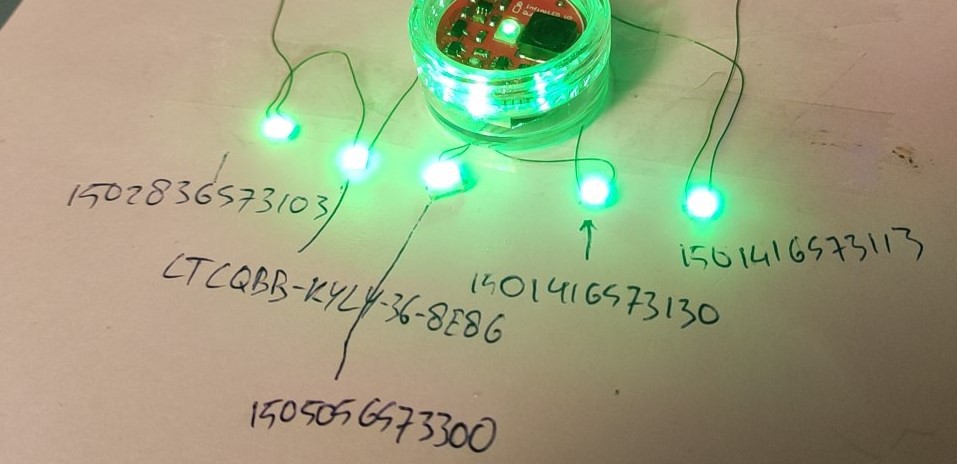
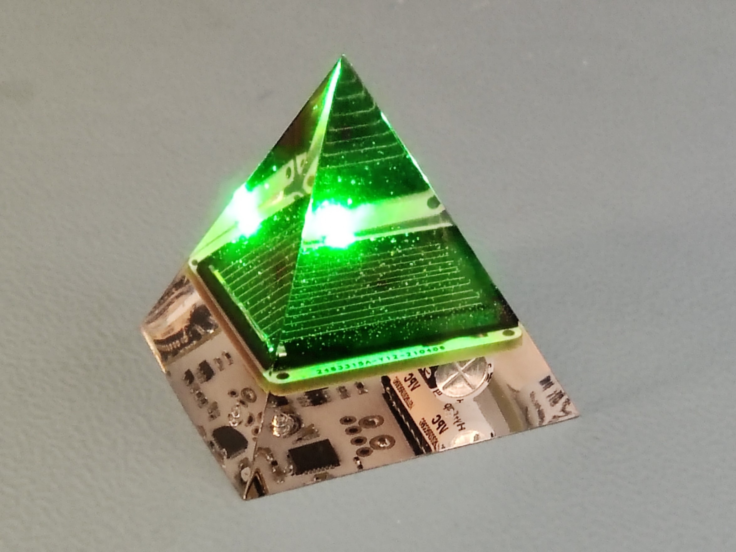
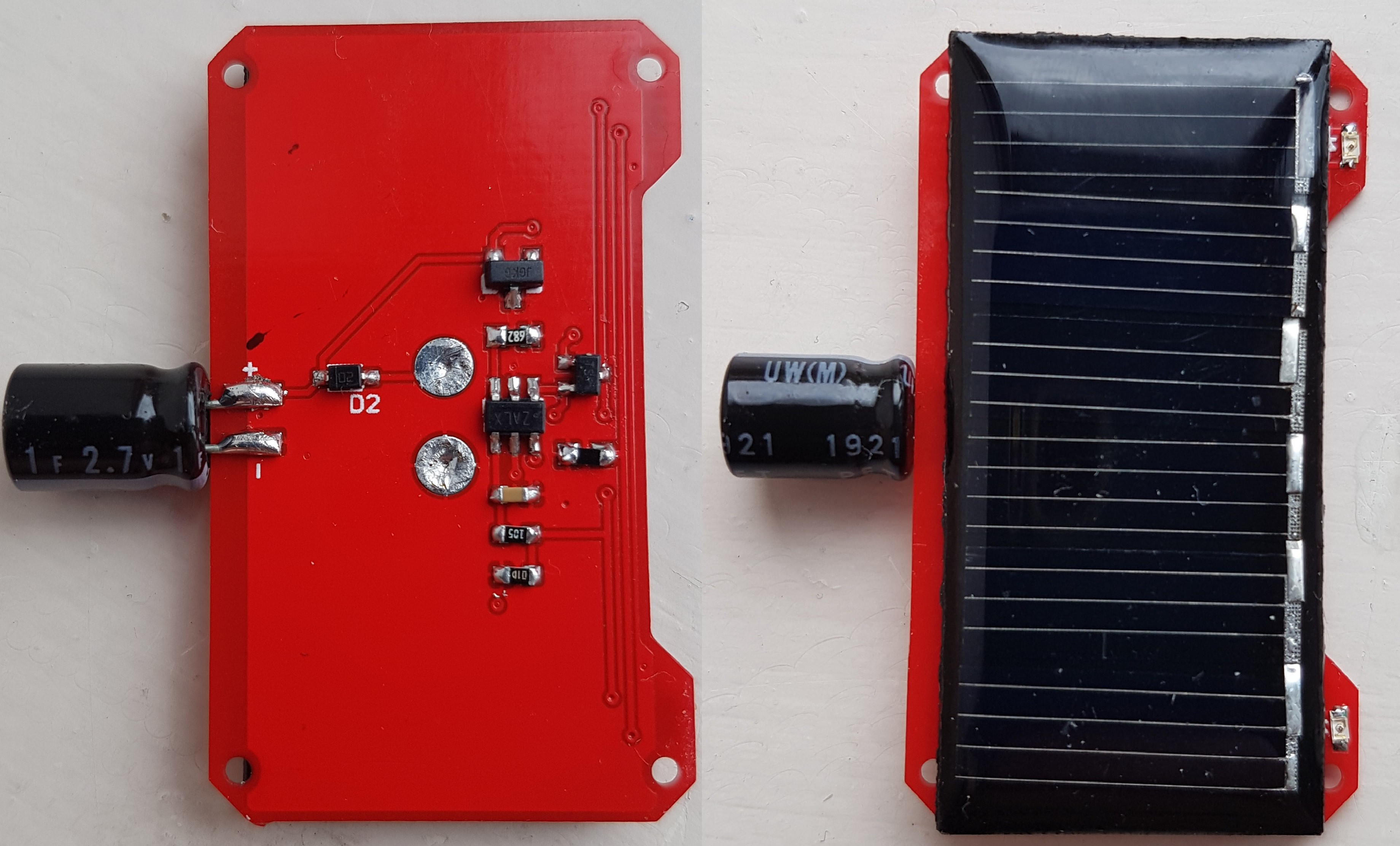
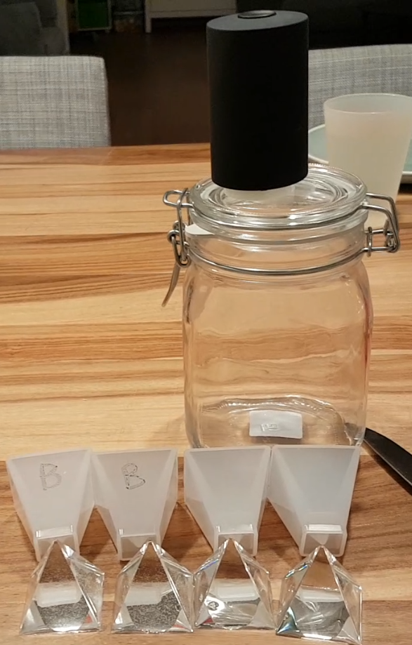
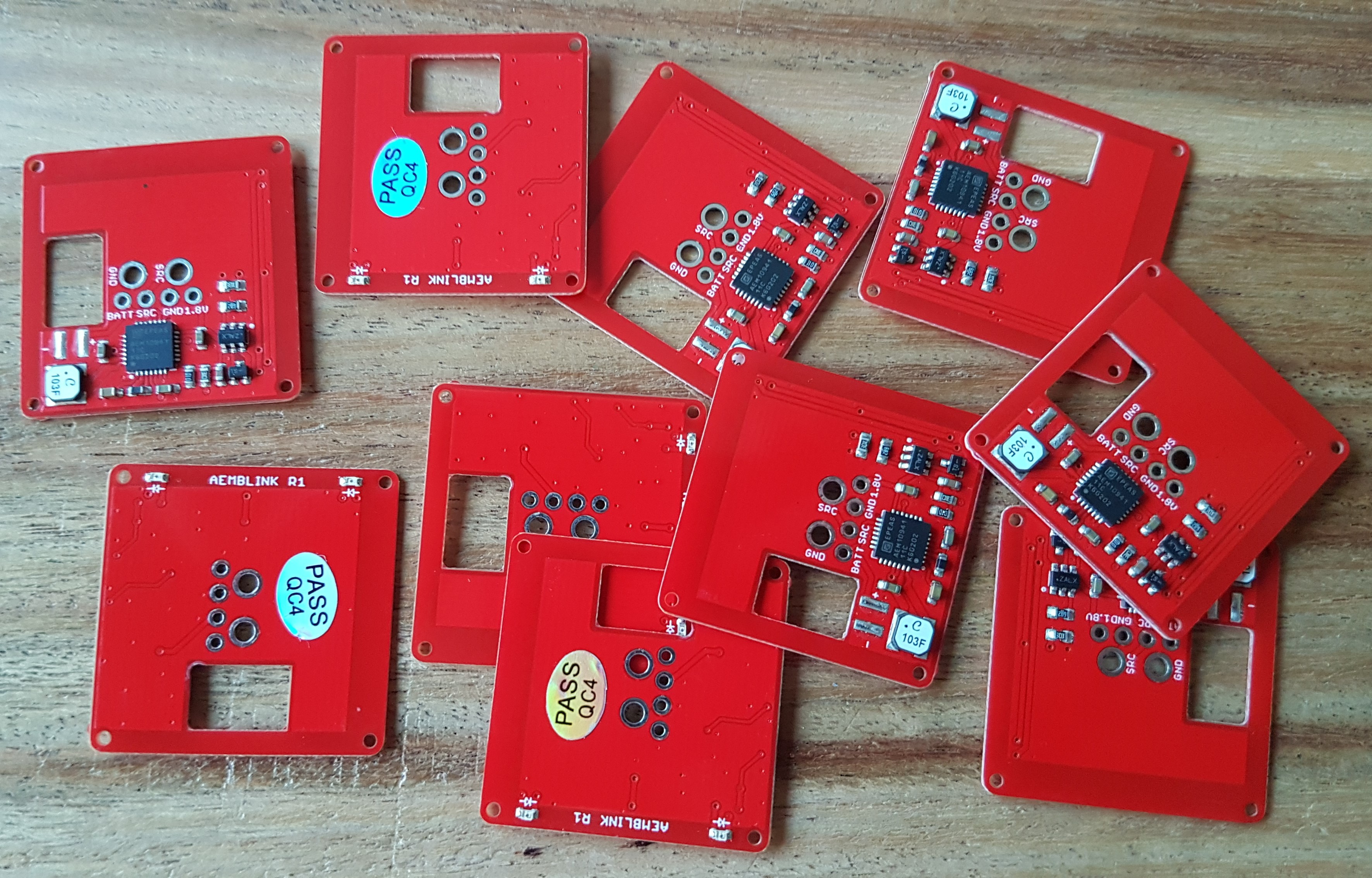
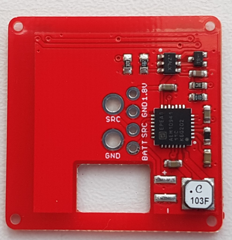
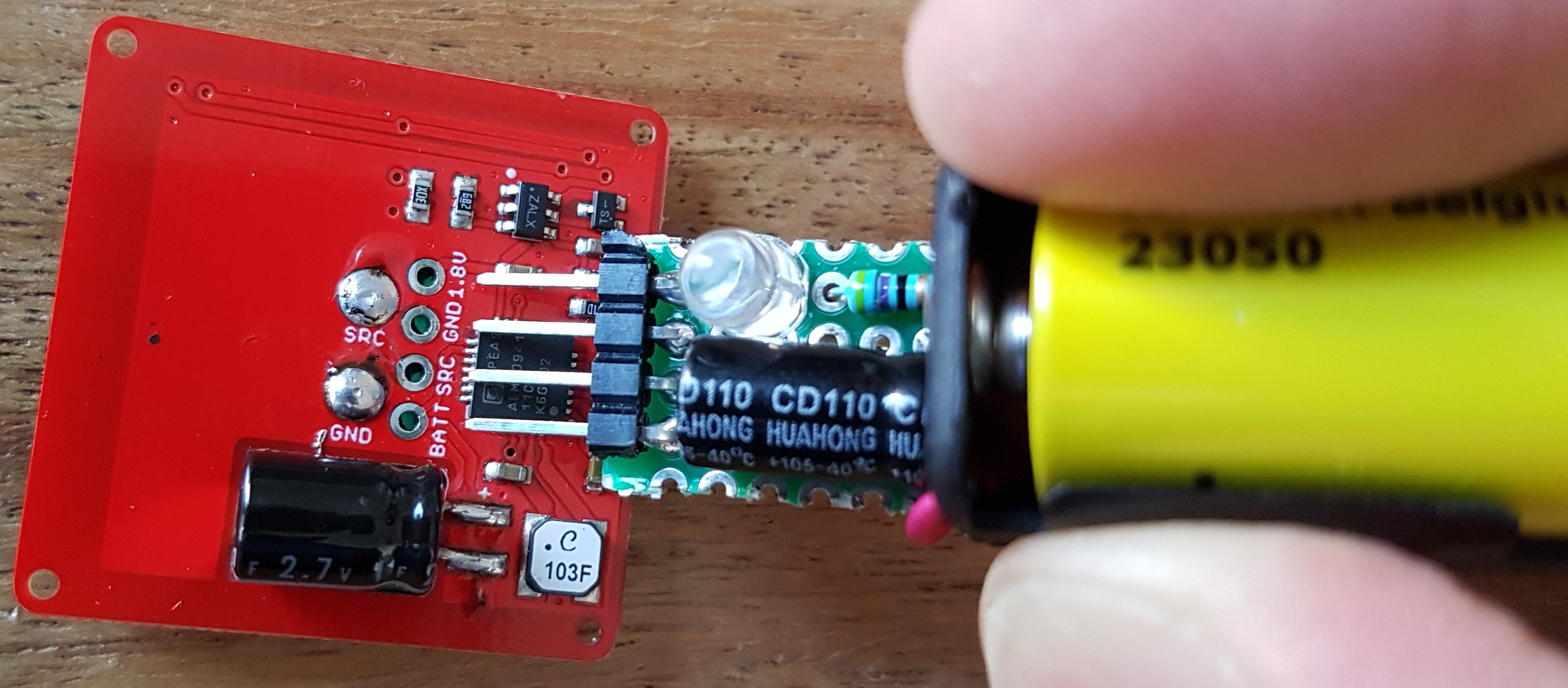
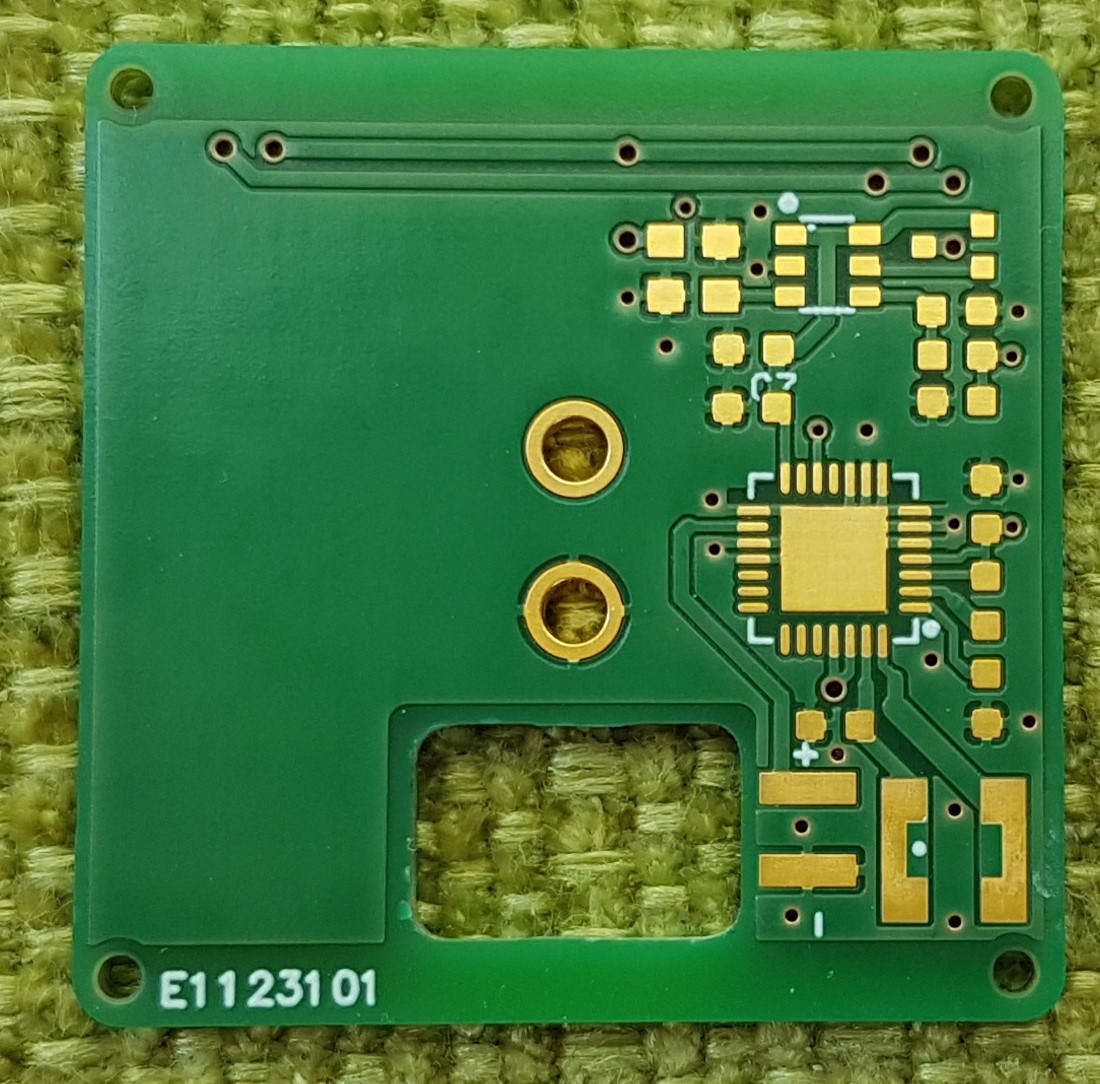
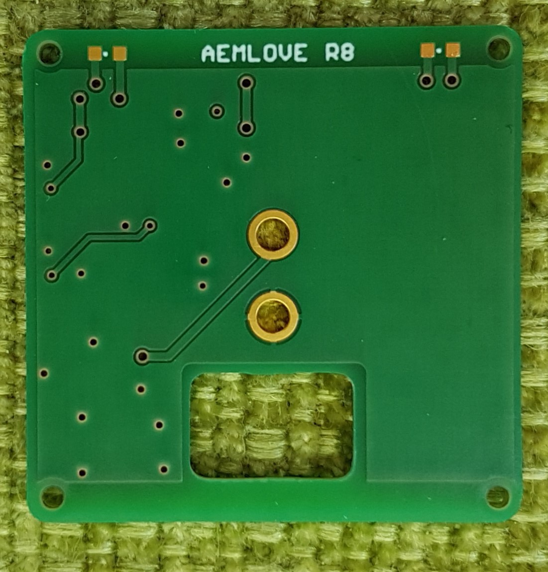
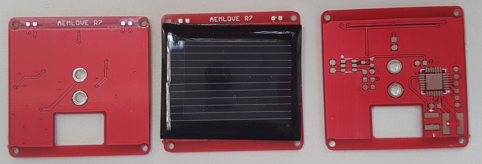
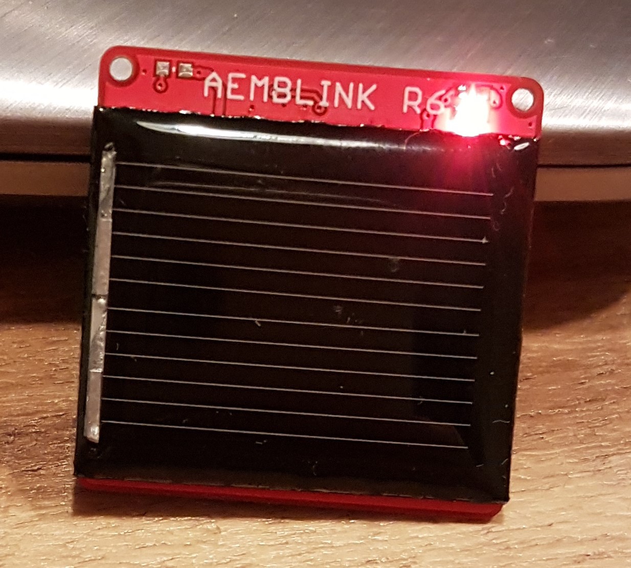
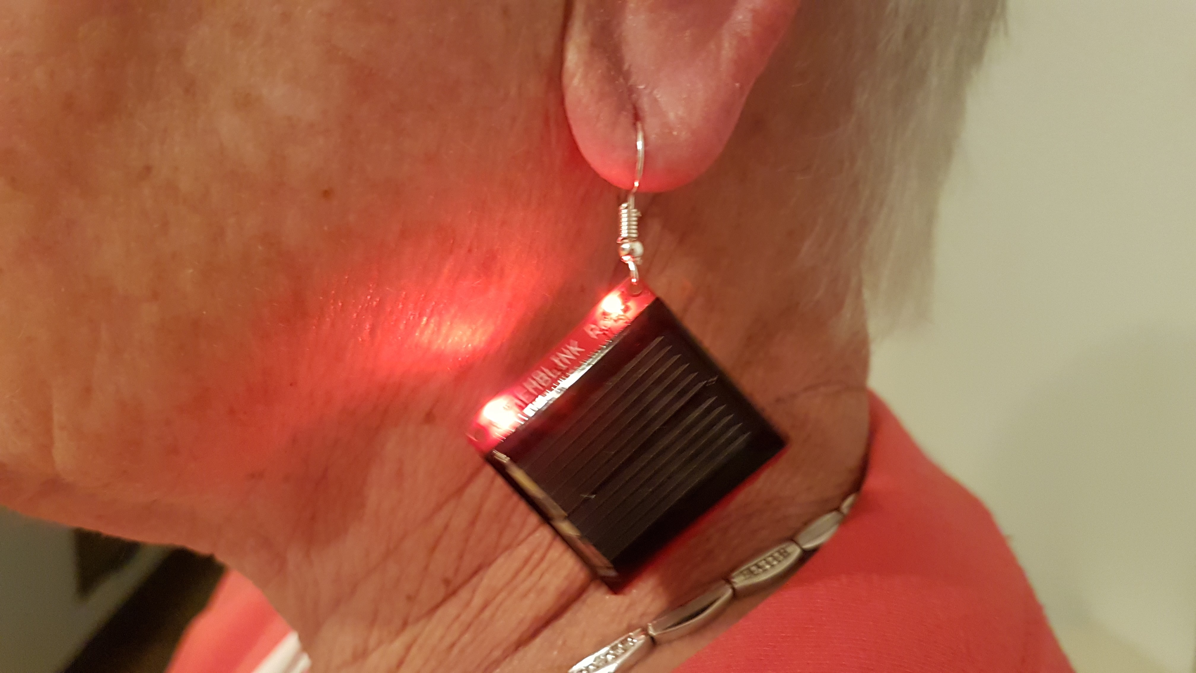
Designing a solar harvesting blinking gadget
Based on earlier solar harvesting projects I wanted to design a solar harvesting gadget
 Jasper Sikken
Become a Hackaday.io member
Already have an account? Log in.
Just one more thing
To make the experience fit your profile, pick a username and tell us what interests you.
Pick an awesome username
hackaday.io/
Your profile's URL: hackaday.io/username. Max 25 alphanumeric characters.
Pick a few interests
Projects that share your interests
People that share your interests


 Tim
Tim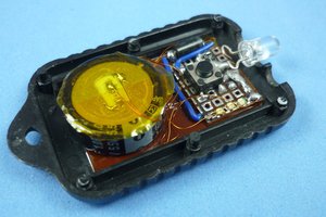
 Absolutelyautomation
 Open Green Energy
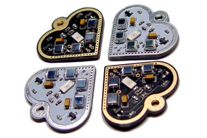
 bobricius
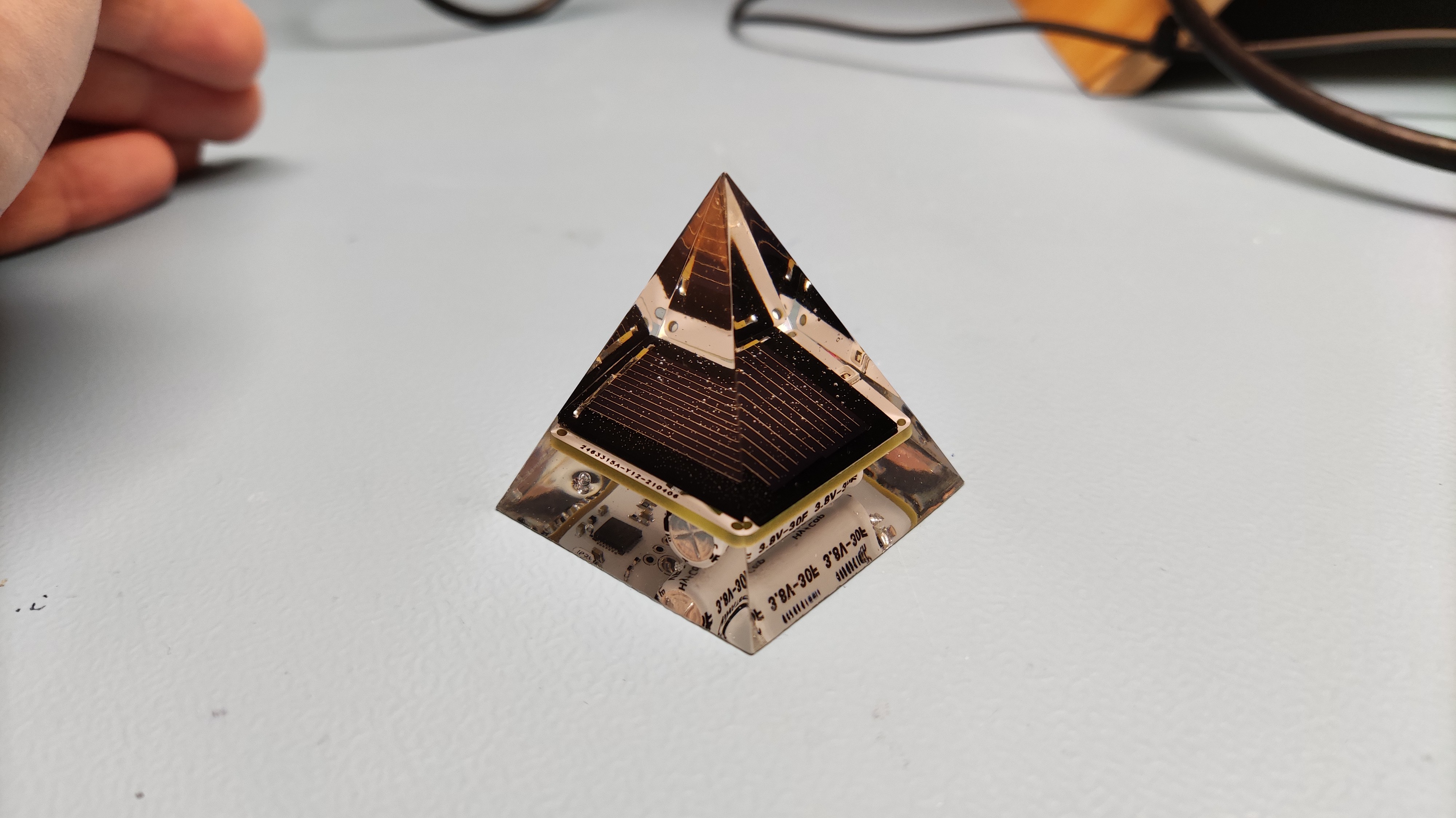
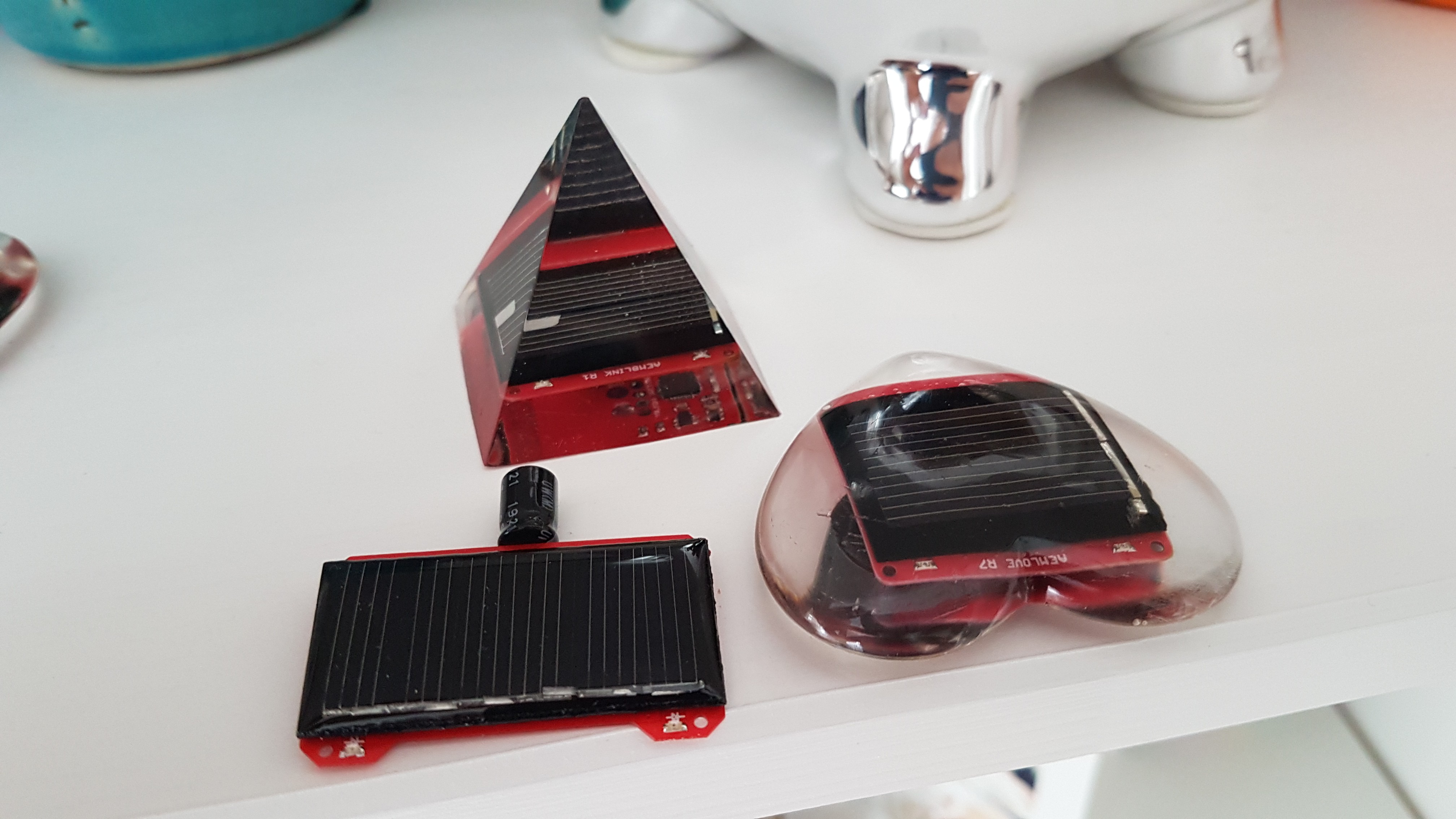
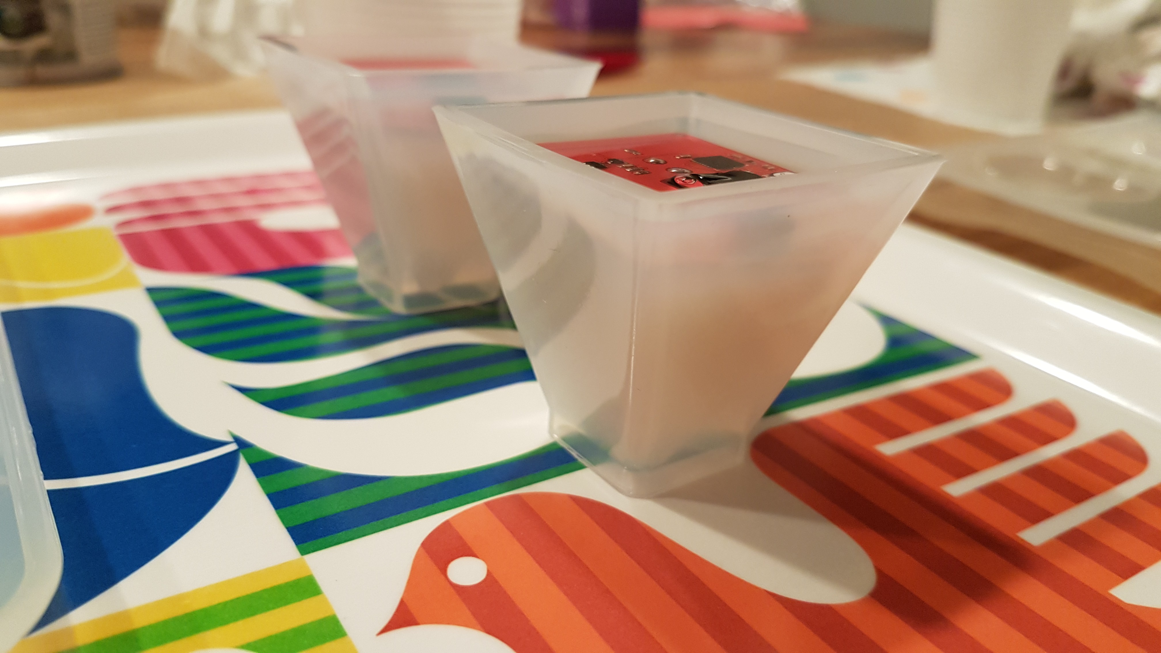
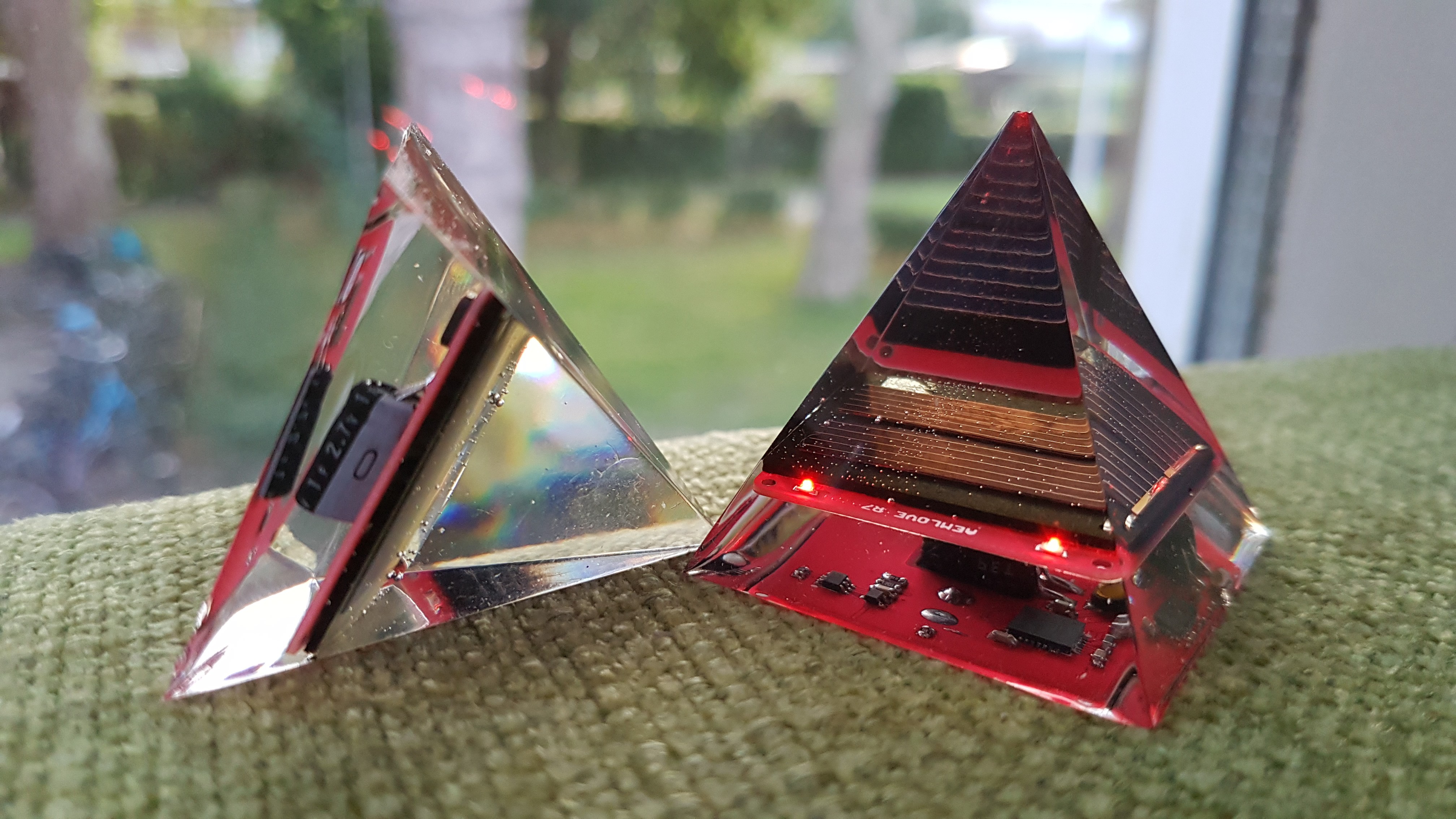
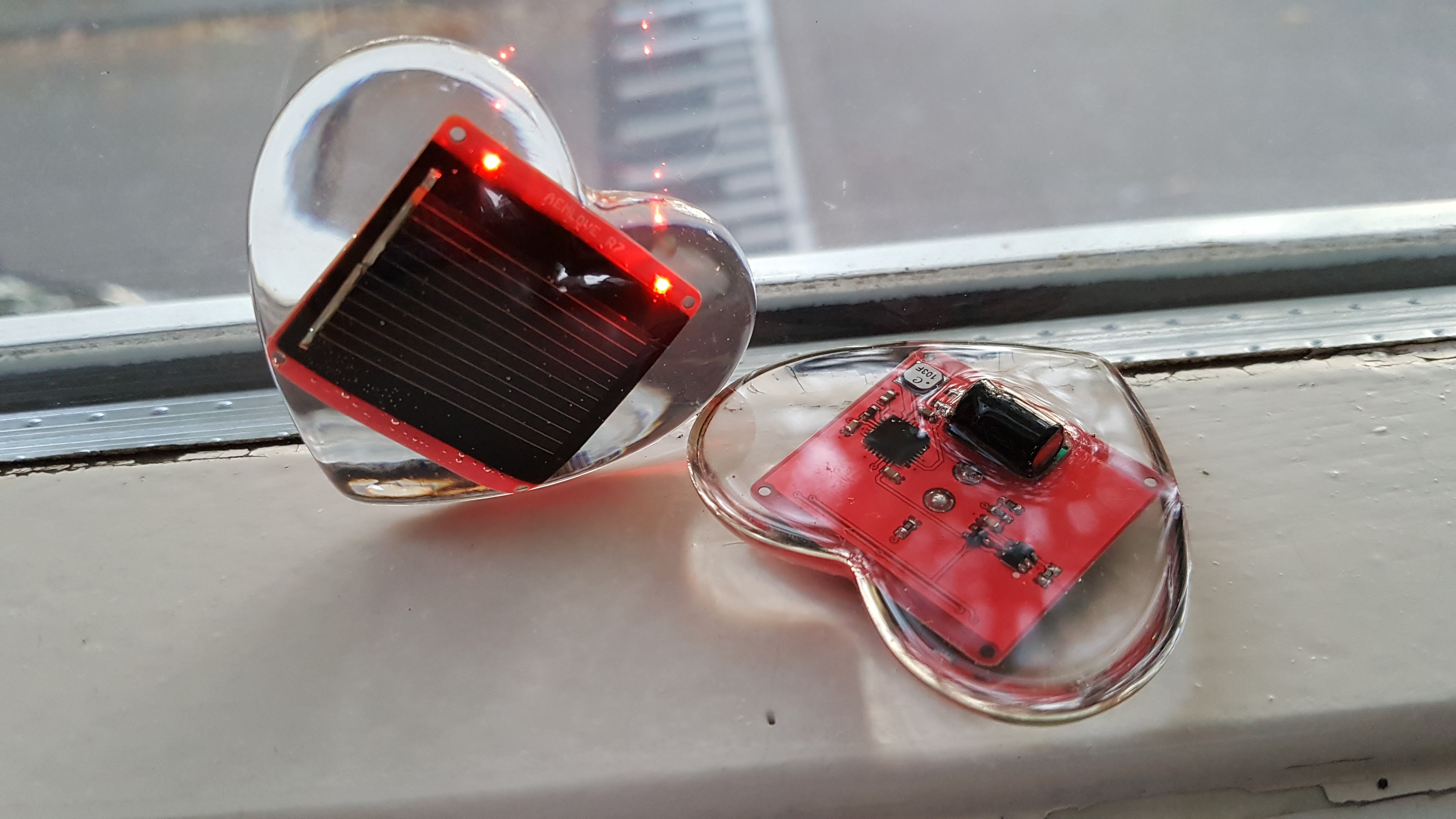
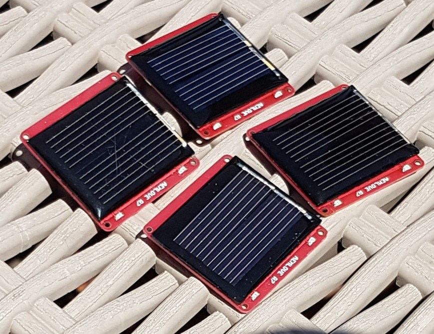
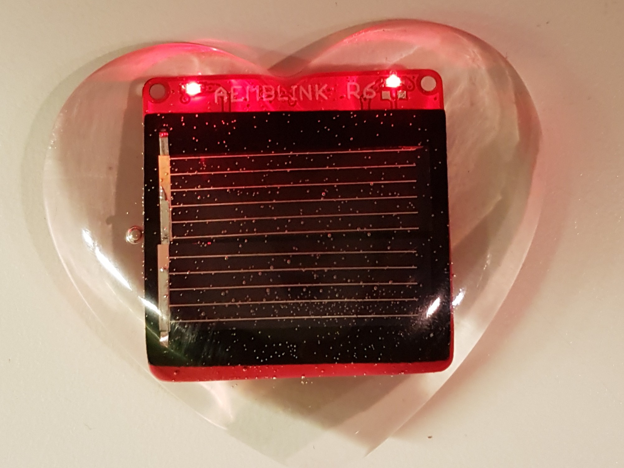
I used a silicone shape from Alirexpress and super clear two compound epoxy resin