 Jasper Sikken
In the previous versions I didn't like the LED blink interval (5s) and the ON duration (80ms) was fixed. I have read somewhere (sorry for no link) that the human eye/brain perceives a 10ms long pulse as full brightness and that flashes with an interval between 0.5s-5s strongly pulls attention. And so I can reduce average consumption while drawing more attention. I found that the TPL5110 "Ultra Low Power Timer with MOSFET driver" that is also for sale on Adafruit and Sparkfun was a great choice to make a bright and low power flash that draws a lot of attention. This is a timer IC ideal for low power applications. Normally it is used to power gate applications and power it ON at a programmable interval. In shutdown it consumes only 35nA. I can choose the blink interval between 100ms and 7200s by choosing a resistor value. This IC is intended to be connected to a microcontroller that sends a DONE signal to the chip when it is done performing its task, for example sending a sensor value wireless, and then it is completely powered off until the timer expires. In my application I don't have a MCU but a simple LED that is powered on. I wanted to feed back the power signal through a RC low pass filter to the DONE pin
Design changes in revision 7
- Instead of using the status2 pin from the AEM10941 to blink the LED I have used the TPL5110
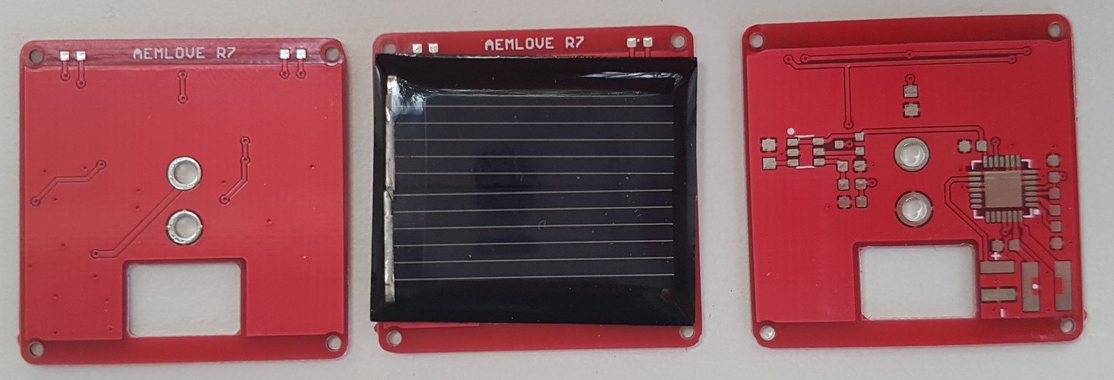
- I made the PCB rectangular (30x30mm) and put the solar cell in the middle of the board
- disabled the AEM10941 LV output (1.2V) because it saves some power and one 10uF capacitor
- make place for an adhesive pin so it can be used as a badge
- put 2 LEDs on opposite side of the board
- changed back to 1 mosfet for 2 LEDs
- remove copper pour around the LEDs so that reflected light can transmit through the PCB
See the schematic below.
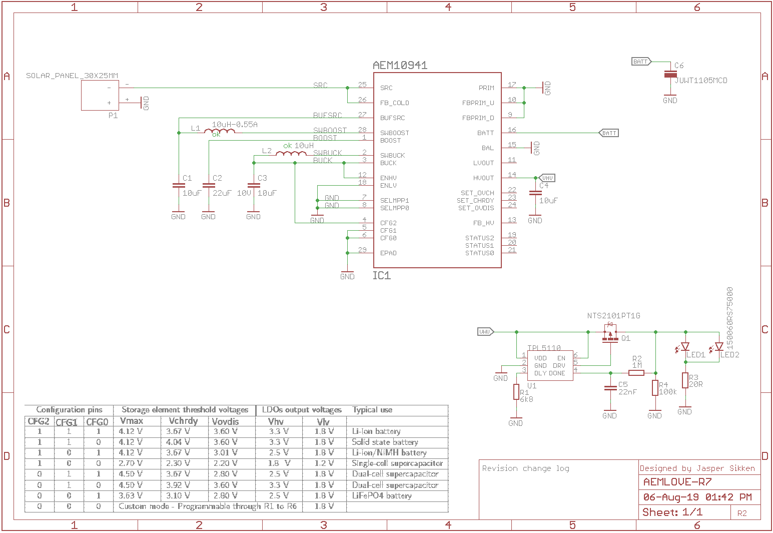
On bottom right you see the TPL5110 circuit. The LED is power gated through a P-channel mosfet. The LED current flows through a 20R resistor and two LEDs in parallel. The power gated signal is fed back through a RC low pass filter to the DONE pin. The DONE pin is considered high when the voltage exceeds 0.7*VDD. With a 1M/22nF the RC time (63%) is about 22ms and close to the desired 10ms. A 6.8kohm resistor sets the interval to ~2seconds. I have added a 100k pull down to the feedback signal to make sure the RC filter capacitor is discharged before it is re-enabled after 2s.
The PCB wihtout any components assembled and a solar panel for reference
I have used the to measure actual LED pulse duration and current from the supercapacitor.
You can see a video of the device actually blinking here. https://twitter.com/jrsikken/status/1137466544555008000
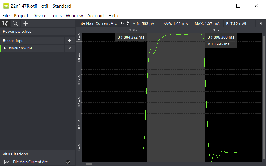
And it shows actual LED was ON for ~14ms. I have experimented a it with the RC values and found shorter pulses were actually perceived as less bright and taking into account tolerances on the capacitor value so I sticked with 14ms.
The average current with the 47 ohms LED series resistor was 6.8uA acording to the Qoitech Otii Arc. I calculated that with a full 1F supercapacitor and 0.5V voltage drop the LED would blink for 20 hours which is far more than the desired 8 hours.
I have changed the series resistor to 20 ohms which gave 1.6mA peak current and 9.6uA average current. Then the LED flashes were nice and bright and the blinking would last 14 hours which is great.
Then I built 4 devices to test actual charge time in full sun and blink duration in the dark.
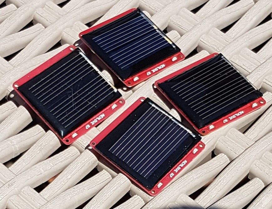
I found at 800W/m2 it takes only 5 minutes to fully charge the super capacitor and they kept blinking in the dark for ~10 hours! This is less than the expected 14 hours. So I need to check what is going on.
What I've learned and can improve:
- I really like the circuit with the TPL5110 because flashes are bright and draw a only 10uA average current while still drawing attention
- the blinking duration was actually ~10 hours while 14 hours was expected. I need to further test this.
- I also like that the board does not have copper pour around the LED so that any reflected light can transmit to the other side.
- the supercapacitor fully charges in about 5 minutes in full sun
- I need to redesign design the board for testing. After PCB assembly and before soldering supercapacitor and solar panel it needs to be tested. And so I need 3 test points: one for the solar panel input, one for ground and one for the supercapacitor
- I want to prepare the board so that people can add their own electronics, so I want solderpads on the 1.8V output of the board and make some space for ie. a bluetooth module.
- that means before being able to sell them I make another revision of the PCB, but maybe this time I have Elecrow assemble them.
Discussions
Become a Hackaday.io Member
Create an account to leave a comment. Already have an account? Log In.