• Control Board on Order

    morgan06/07/2019 at 15:44 0 comments

    I've been working my way through the control board, finally happy with the design and have sent it off to @oshpark.

    Not a lot has changed since the previous post on this board, I did finally decide on the LSM6D as it had several things going for it.

    1) Having a 3-deg gyro will allow for more flourishes when 'casting'

    2) 3 extra degree, plus temperature was only $0.40 more ($2.6>$3)

    3) I have 3 or 4 of them already.

    I got all the important signals broken to test points on the backside. I've been wanting to give this Open Fixture a try. Apparently it runs some scripts on board file that get plugged into an OpenSCAD script to general a test jig to be laser cut. Sounds handy and something I should learn.

    I also made sure to hook up the LSM6D to the ESP32s RTC_GPIO pins. This will allow me to configure it to wake up the CPU from deep sleep. The goal was to do some light weight motion detection in the ULP but as it doesn't support interrupts that wont' happen.

    The Micro-32 modules should arrive tomorrow, I expect there should be no surprises there, I got technical drawings from the seller that matched the footprint I found. But if anything does go wrong, I should have a window to cancel my order.

    MOCK UP!

    I've been trying to get a nice rendering going but still have some figuring out to do with FreeCAD/Pov-Ray but this should give a general idea of the proportions. The final board was a bit shorter (save a $1!) but should still fit the handle nicely, which I think will come out at about 3.5" (127mm).

    Alright, that's it for now. With boards inbound next thing is to do some tests to see how small of a tube I can run my wiring through. The mock up has 3.1mm which kind of dwarfs the Sprite. Might look okay? We'll see!

  • Ideal Pad Placement/Draw String Closure?

    morgan05/28/2019 at 04:49 0 comments

    Alternative post title: And Another Thing....

    I've still been mulling over the ideal pad placement and keep thinking if I try to mount the cube to the tube, internally and as a connection, the cube won't sit the way I want. Rather than to opposite corner being perpendicular to the tube, one of the walls or an edge would be.

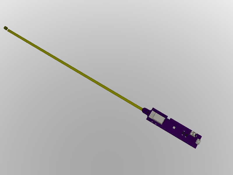
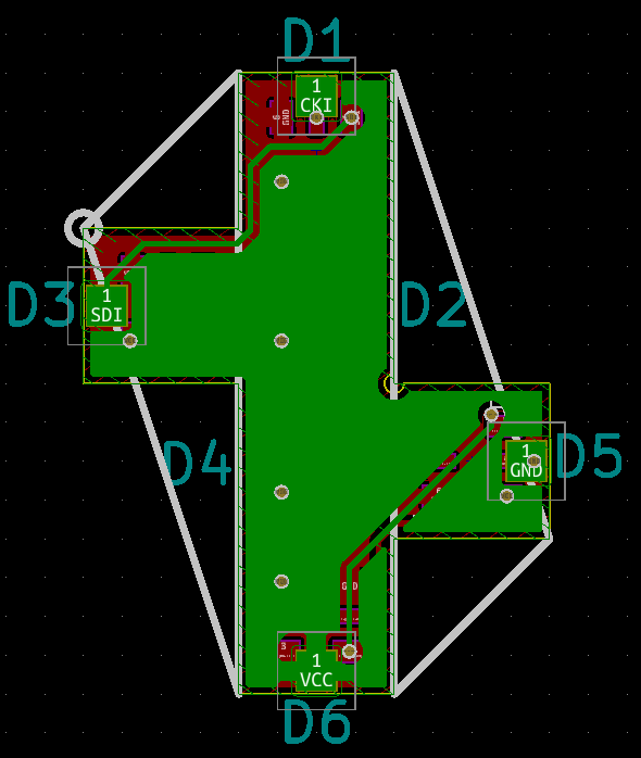
    I figured it made the most sense to run 4 wires through the tube and only connect the tube for a structural connection. I need to get some more tubing in order to determine how small a tube I can get away with, while allowing all 4 (3 is *reeeeally* needed) to pass thought it. Once I have that I can appropriately size the hole below D2. This will need exposed copper around it to hold.

    Aaaaaand there isn't a lot of room.
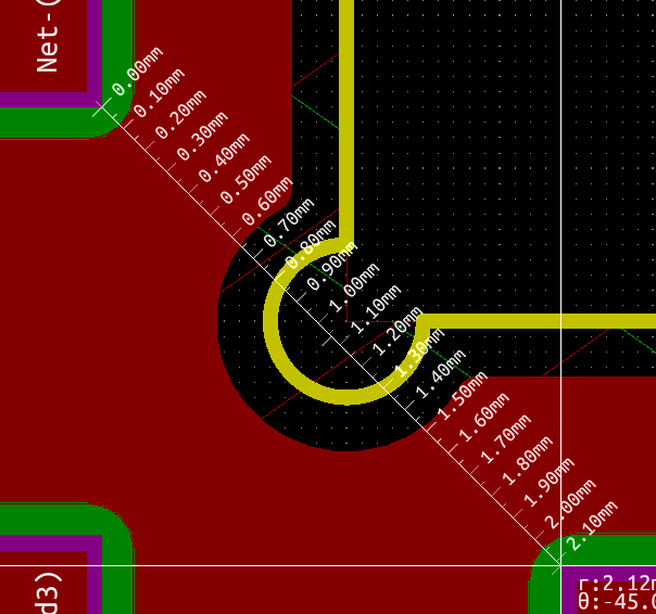
    The OD of the largest tube on #Venusian Star Palm is 3mm... If I'm unable to get 3/4 wires down a <2mm (yeah, more like 1.5mm with clearance) I think I can add 3 solder tabs to make contact with the tube, then that cutout will be strictly to bring the wire inside the cube.

    BONUS!

    As I was working my way though this I realized it is only a few modification away from being a blooming flower. I don't have the time for that right now and will stick to my original plan.... but it's a good starting point.


    Or.....

    This was realized quickly enough I'll just go with an edit...
    If the tabs are in fact needed, I will do away with that circular opening and flip the cube. This will allow 3 full sized tabs to solder to.

  • More Deisgn Files

    morgan05/28/2019 at 03:03 0 comments

    I've added the design files for the controller portion of the project. I decided to just lay out a basic board as an excuse to try out these Micro-32 modules I ran into. Right now the board uses an LIS3DH but I'm still waffling on LSM6DS3H (mostly because I have a couple). Got a couple small things to do, add programming header mostly and I think it'll be ready to go.

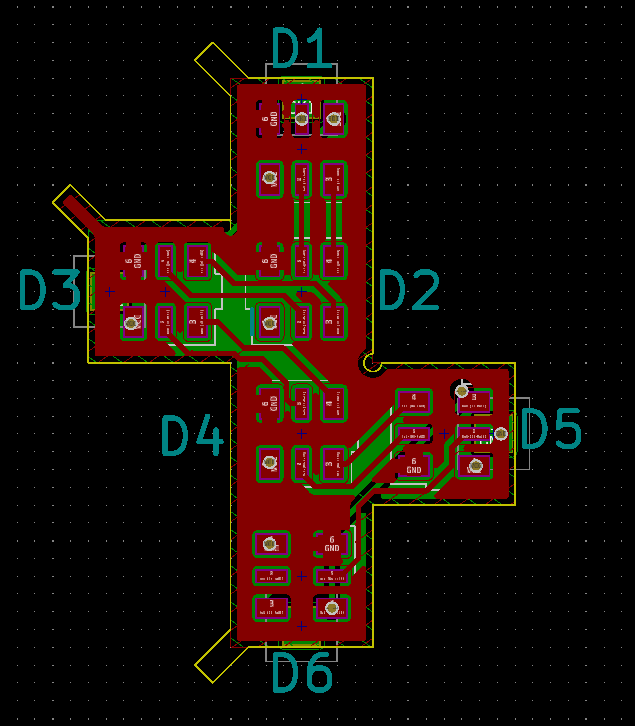
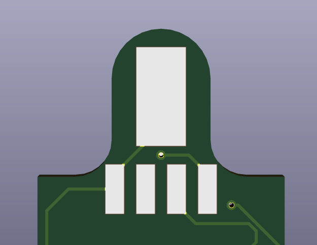
    I decided to go with a single tube and run 4 wires for simplicity. The large pad is for mounting the tube but is also connected to pin 1 (GND), if 4 wires is too snug, I can use the tube itself as GND.

    Other than that the board is pretty straight forward. The Micro-32 module is quite nice as it's only 13mm wide! I plan to mount this inside a wooden handle, the overall board is only 20mm wide and will be paired with my present favorite 500mAh lipo coming in at about 15mm wide.

    I'm shooting for a handle diameter of around 25mm but will depend how I end up cutting the compartment to house this.

  • Early Attempt/Leave it to the Pros

    morgan05/27/2019 at 21:49 1 comment

    At the end of last year I went on a bit of a home etching binge for my entry into the Freeform Sculpture Contest, #Venusian Star Palm. Turns out, Pyralux is quite a bit easier to home etch than FR4, not sure why though.

    When everything was done, and I slapped together a write up no one read, I was still setup for etching and had the house to myself for a couple more days. So thought I'd give this cube a go.


    Not toooo shabby. But the edge connections where just too small and the tolerances where just too tight and I ended up with a significant number of defects. If I'd had more faith in doing proper double sided (over just two larges 'traces') it might have worked out better but looks cool.

    With potential for a proper cube through @oshpark I will also utilize something I learned while making #Venusian Star Palm, wire in a tube in a tube. The plan is the mount the 'sprite' on the end of a brass tube, that has another insulated brass tube inside it, which has two magnet wires running inside it.

    Here you can see the magnet wire carrying DATA IN, inserted into a brass rod carrying VCC insulated with kapton interted into another rod carrying GND.

    With that same inner tubing, getting two wires didn't seem like it would work, so I'll either go with 3 or all for in the larger if it comes to it.

    The rest of the plan is to build a nice wood handle for it, chuck what ever micro and hopefully an accelorometer in there and call it a project!