 dsl
dslAlmost a month and a half passed since the previous update (not so much comparing to v0.3, eh?) and I'm here to share some details regarding the overall progress.
First of all, I've finally got rid of the leading zero in the Xling PCB version because there are no chances that I'll be brave enough to change it in future. So, v0.3.1 became v3.1 and it means that the most recent changes of the Xling PCB will find their way into current/3.0 branch of the repository.
Note that it has nothing in common with the firmware version of Xling. The most recent changes in code find their way into current/0.4 branch of the Xling-firmware repository
Animation demo
Anyway, I'd like to show you a walking animation demo at 24 FPS. There are only 4 images of the animation where each one stays on a screen during two frames.
However, a driver for SH1106-based displays I've been working on can do its best and produce the same animation at full speed:
You're probably interested in the technical information on the screen. Here it is: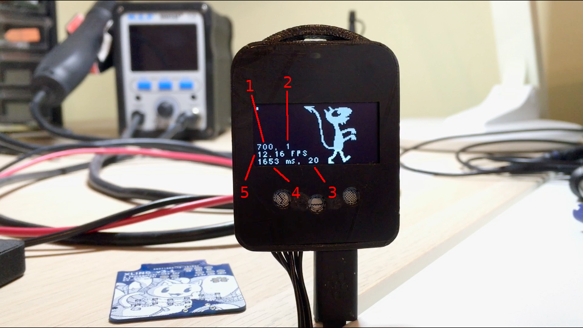
- BAT_LVL - a raw ADC value of the battery voltage (voltage divider, ADC3, 10-bit, Vref = 1.1 V).
- BAT_STAT - a single bit, which is grabbed directly from the MCP73831 STAT pin (1 - when the battery current, Ibat, is below a selected threshold, Iterm, 0 - otherwise).
- Number of frames to re-draw before calculating a delay.
- Time spent to re-draw the frames.
- Current FPS (according to 3 and 4).
More PCB checkpoints and 4-wire SPI
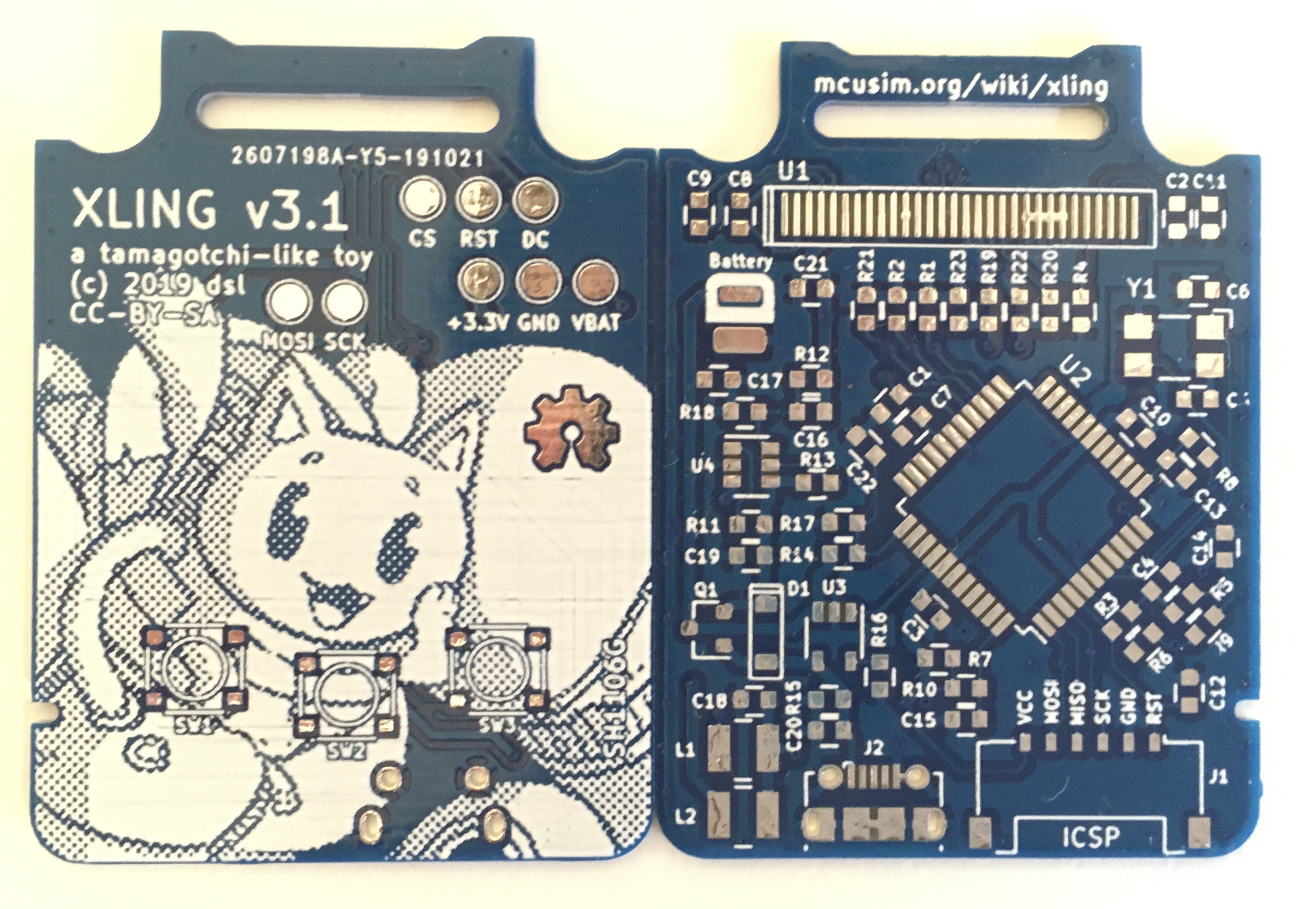
Spending time debugging and optimizing the OLED driver, I've realised that it would be convinient to have additional test points on top of the PCB. It's now possible to solder wires and attach the oscilloscope probes easily, without turning the bottom part of the PCB into a mess.
Another change is 4-wire SPI which is used to connect the display in v3.1. I've decided to give up with the 3-wire SPI support in the driver entierly because of the 8-bit SPI shift register available in ATmega1284P only.
There is no room for the 9th bit required by the display controller to distinct between data for graphics RAM and command register. Moreover, there is no easy way to stop transmitting bits from the shift register to "hack" the protocol.
FreeRTOS-based firmware
Other updates
Anyway, if you have any questions and ideas on your mind, feel free to tell me then.
Have a good time!
Discussions
Become a Hackaday.io Member
Create an account to leave a comment. Already have an account? Log In.