 Boris Landoni
Earthquakes have different origins, but the most plausible reason for them lies in the plate tectonics theory: according to it, the earth was originally formed by a single continent (which would explain why the same animal species may be found in distant, separated continents) that divided itself in the five ones we see today. Technically, we are talking about the “continental drift”, and it has been ascertained that the continents still move today. When the continuous and imperceptible movement of the plates suddenly stops, and energy and tension are accumulated in certain zones for decades or even centuries, at a certain point the tensile strength is exceeded and all the accumulated energy is released in a matter of a few seconds, thus generating a sudden shifting of the rock mass involved, and consequently originating the phenomenon known as earthquake by people and scholars. Even the igneous activity under the earth’s crust is connected to earthquakes.
The detection of the seismic activity, that was once typically carried out by means of electro-mechanical tools called seismographs (and consisting in a stylus mounted on a pendulum, connected to ground, and capable of drawing oscillations that are equal to the strength of the ground motion), in recent times has been successfully entrusted to electronics, thanks to existence of sensors such as the MEMS, that are capable of detecting accelerations on the three axes, with extreme accuracy. Such sensors have enabled the creation of electronic seismographs that we may consider as “solid-state ones”, even though they are based on processors that integrate components that are subjected to micromotion.
The project we are describing in this article is based on a similar sensor and, more specifically, on an Omron component: we designed a ready-to-use breakout board for it, an ideal one for the purpose of prototyping applications and experimenting.

THE D7S SENSOR
The device presented here is the world’s smallest seismic sensor to date, it is manufactured by Omron and is signed D7S. One of its most important features is that it signals – by means of the INT1 pin – seismic events that could have devastating effects on electronic equipment; for example, such a function allows to turn off the said equipment, before the vibrations may actually cause such damages. It is essential to safeguard the machinery in order to be able to still have – after a seismic event – operating devices, in order to prevent further damaging events. By the way, the warning that may be obtained from the INT1 contact could be used in order to activate alarms and – why not – to activate some mechanical protection for the measuring tools and for the places that are hosting them.

The signals emitted by the sensor are two: shutoff and ground collapse. The first situation occurs if the earthquake is deemed of an intensity equal to or greater than 5, according to the JMA’s (Japan Meteorological Agency) seismic intensity scale, and if certain conditions – as defined by JEWA (Japan Electrolyzed Water Association standard JWA) as for the JWDS 0007 standard, appendix 2- are met. The second situation occurs if the ground suffers an inclination of about 20°.
The sensor also has an internal memory that stores the data concerning the five most recent earthquakes saved, and the five greatest ones, in addition – of course – to all the configuration settings.
The D7S is composed of a three-axis accelerometer, only two of them are used during the detection of an earthquake, and may be selected by both the user and automatically, with respect to the sensor’s inclination. The presence of a I²C bus enables the modification of the sensor’s settings, or to read the data concerning the earthquakes: this may be carried out by any microcontroller supplied with the abovesaid bus, and from Arduino as well. Overall, the D7S sensor is supplied with three function pins; two of them (INT1 and INT2) are signal pins and the third one (SET) is a line used in order to modify the operating state.

Before using the sensor it is necessary to carry out the initial installation procedure, that is to say that the sensor has to detect the offsets for the selected axes, and to save their values to the internal memory; such offsets will be used in order to distinguish the collapsed condition, so to compare them with the current ones when detecting the seismic event.
After the initial installation, the sensor will enter the standby mode until an earthquake starts, when the calculation of the data concerning the seismic event starts; it remains in such a state until it deems the earthquake has ended. At this stage, the internal memory is updated with the recently measured data.
Each time it is powered, the sensor is brought to the offset detection mode, and it determines if the collapse condition has been met and, if so, it alters the logical condition of the INT1 pin, by setting it to the low level. If the condition is not met, the sensor enters the standby mode and the earthquake detection cycle starts.
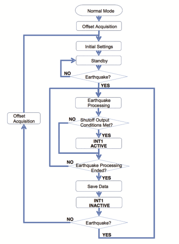
It is good to specify that the verification of the collapse condition does not occur only when turning on the sensor, but every time the sensor enters the standby mode; it is still possible, in fact, to force the control of the collapsed condition by bringing the sensor to the offset acquisition mode.
The data calculated by the sensor for each seismic event includes the PGA (Peak Ground Acceleration), the SI (Spectral Intensity) and the average environmental temperature at which the event occurred. During the calculation, that is to say, during the earthquake, it is possible to read the instantaneous value of PGA and SI, by accessing some specific registers.
Inside of the sensor, a self-diagnostic function has been implemented: it is very useful in order to verify if the D7S correctly operates, but it must be manually activated by writing a register, by means of the I²C bus. For each offset acquisition, the sensor automatically defines if the operation was successful, otherwise, it updates a specific register, and consequently warns of the malfunction.
The sensor’s functional pins are INT1, INT2, and SET: the first one corresponds (as already pointed out) to the signalling of the shutoff and collapse conditions, while INT2 enables us to know whether the sensor is in standby mode, if it is in the earthquake detection mode, if it is acquiring the offsets or if the self-diagnostics function has been activated.
SET, the last pin, enables to bring the sensor – by means of an external pulse – to the initial installation mode, and without having to resort to using the I²C bus.
When the INT1 pin is brought to the low logical level by a shutoff or collapse event, the default value – that is to say the logical 1 – may only be restored by reading the EVENT register (please see the next paragraph), by carrying out the initial installation procedure, or by switching off the sensor.

More info: https://www.open-electronics.org/earthquake-alarm/