 Cees Meijer
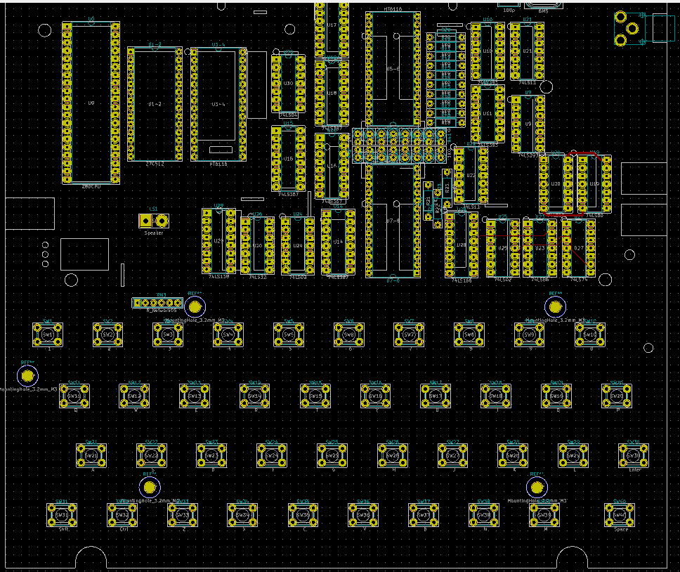
After I placed most of the ICs on the PCB, mostly according to the original layout, I started to try and route them. And by following the routes by looking at images of the original PCB it seemed quite simple. But when routing what looked like power and ground it suddenly struck me that two pins on both corners were connected. Since I have worked a lot with ICs of the 7400 series in the past I knew that most of them had Vcc and GND on two outer corner pins so this did not seem right.
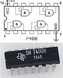
A closer look at the traces that connected the corners also showed that these did not have a net name. On the schematic there are also no power pins for any of the 74xx chips. But all Kicad guides that I could find also mentioned that power pins for logic chips are always hidden, and automatically connected to VCC and GND. There is a 'Show Hidden pins' button, but clicking it does not reveal any pin on a 74xx port. On the PCB it looks like all power and GND pins are simply connected by a net that has no name. This really puzzled me for while, until I discovered that all 74xx units actually have an extra unit that contains the power connections. So the 7400 contains 4 ports (Unit A,B,C,D) and a Unit E which only contains VCC and GND.
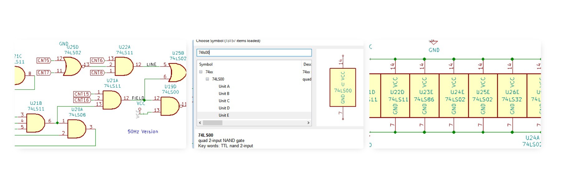
After adding the power 'unit' for every chip, the PCB routing suddenly makes sense and the pins are also marked with their correct names.
Discussions
Become a Hackaday.io Member
Create an account to leave a comment. Already have an account? Log In.
Thirty years ago it made a lot of sense to hide the power pins of the IC's of common logic families.
* Power pins were (nearly) always on opposite corners.
* All those power pins had the same voltage.
* There could be hundredths of those IC's on a big PCB.
None of those "rules" apply anymore.
* PCB's have far fewer (but more complex) IC's.
* Even a single IC can have multiple different supply voltages.
* Even 74HC logic can have somewhere between 3V and 6V power, and it's not certain all should be the same.
* Power pins have moved to other locations for better EMC performance.
Are you sure? yes | no
>But all Kicad guides that I could find also mentioned that power pins for logic chips are always hidden, and automatically connected to VCC and GND.
Any guide that says that is way out of date. Unfortunately there are a lot of old articles and videos still floating around that are for older releases. It's the old 74xx libraries that have hidden power pins. This is a deprecated practice now. All recent libraries use power units.
Are you sure? yes | no
Yes, thanks for that hint too; that was quite counter-intuitive ;)
Are you sure? yes | no
Thanks for the hint! I've never used a 74xx chip since a make PCB with KiCad but it's just a matter of time (I certainly have plenty of them lying around).
Are you sure? yes | no