 Cees Meijer
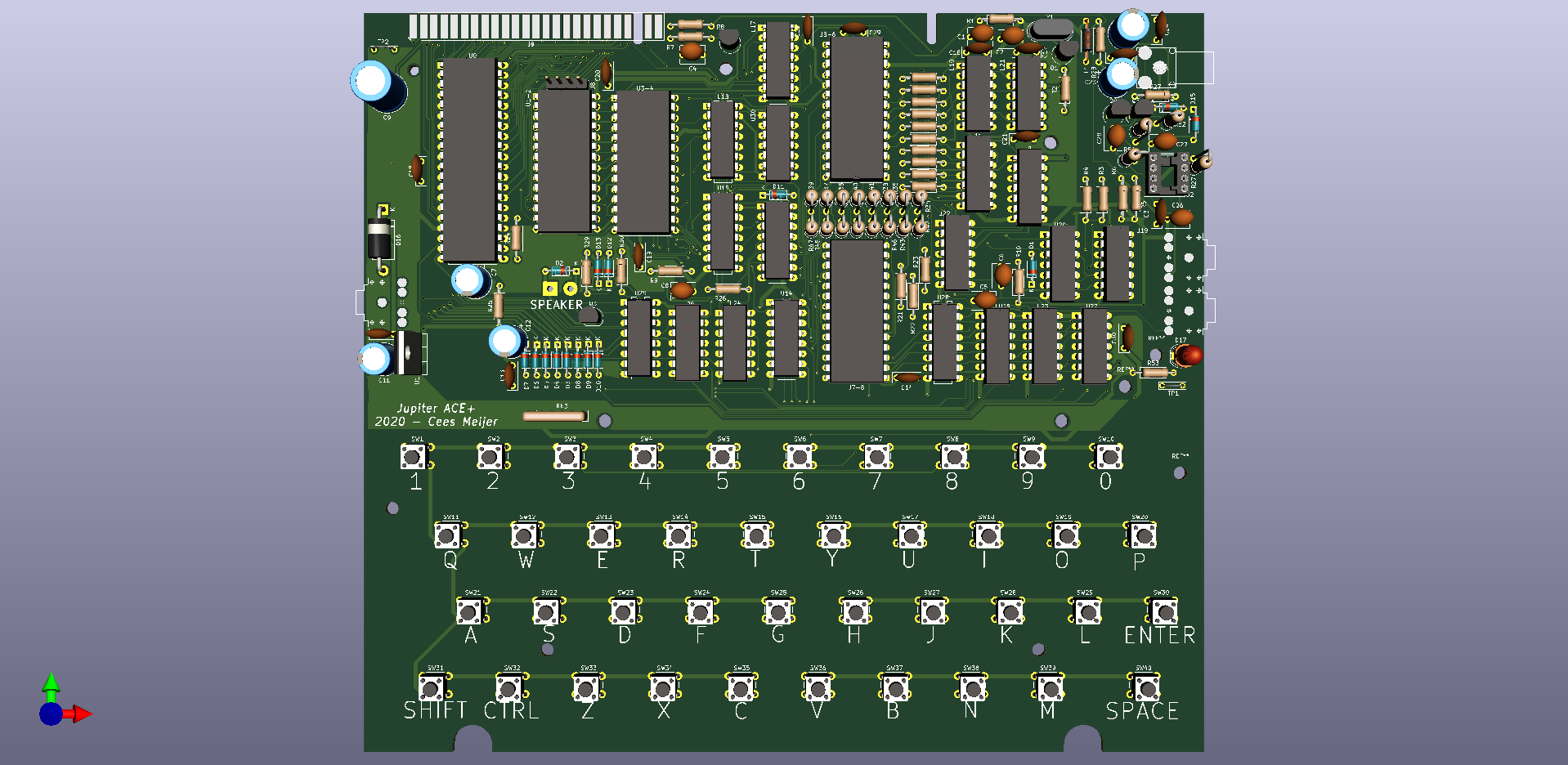
Now the routing is complete, and the moment where I have to send the design in for PCB production, it's time to go over the last details.
Decoupling capacitors
Someone mentioned that not all chips have a decoupling capacitor, and that could lead to problems. So I went over it and placed some extra 100nF wherever there was still space.
Silkscreen
Next, I added the letters / figures to the keys so they would be visible on the silkscreen. I first made all text in font-size 2x2, which seemed big enough on the screen. But when I printed the board 1:1, they appeared a bit small. So I found that the KiCad PCB file format is actually text, and that it was really simple to do a search / replace action to change the font size.
Footprints doublecheck
Checking the few footprints I was not sure of. Especially the transistors are notoriously difficult to get right. Countless are the boards where you have to mount the transistors backwards, on the bottom or worse: with two pins crossed. I also had my doubts about the 3.5 mm connectors for power and audio, but they matched perfectly on the paper printed layout,.
Zone fill for Vcc and GND
Added a few more 'zone fills' for VCC and GND. So far I routed all power lines using 1mm traces, but that is not much and could possibly cause problems with the (relatively) power hungry TLL chips. So adding a bit of copper here will definitely help.
Check the outlines
I found that I had two board outlines drawings. The first one was the one that I drawn by hand in KiCad itself on the Edge.cut layer, and the second one is the version that I imported from the mechanical drawing (which was more accurate) on the 'Dwgs.user' layer. So I removed all lines from the 'Edge.Cut' layer, and moved all relevant lines from the Dwgs.user layer to Edge.cut.
Add Diode and LED
As someone mentioned that the power plug polarity on the Jupiter ACE is different from that on the ZX80/81, I suppose its a good idea to add a diode to the power line. And then, it's always good to have a LED on the board so you can immediately see if the power is actually present.
So, finally, I think it's time to send it to China, and have some boards made. I chose Seeed Studio for that. I've used them a few times before, and the boards are always very nice. The whole process of sending the files and placing the order is described on their site, and it is super simple. And they have their own Gerber viewer, so you can quickly see exactly what the boards will look like.
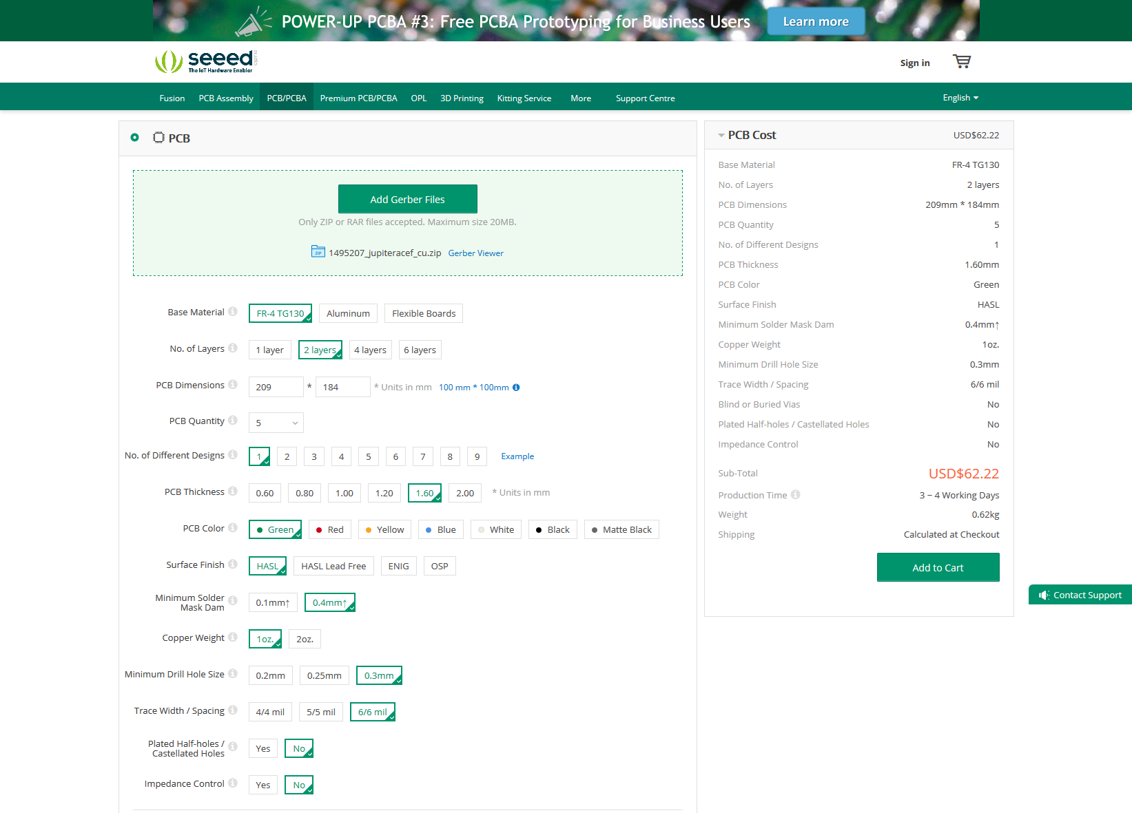
US$62 for 5 pcs. Not too bad. Unfortunately the shipment will be another US$23, so the total will be around US$85,- Still not too bad. Let's hope the board is 100%, and I might be able to sell the extra boards...
Discussions
Become a Hackaday.io Member
Create an account to leave a comment. Already have an account? Log In.