 Cees Meijer
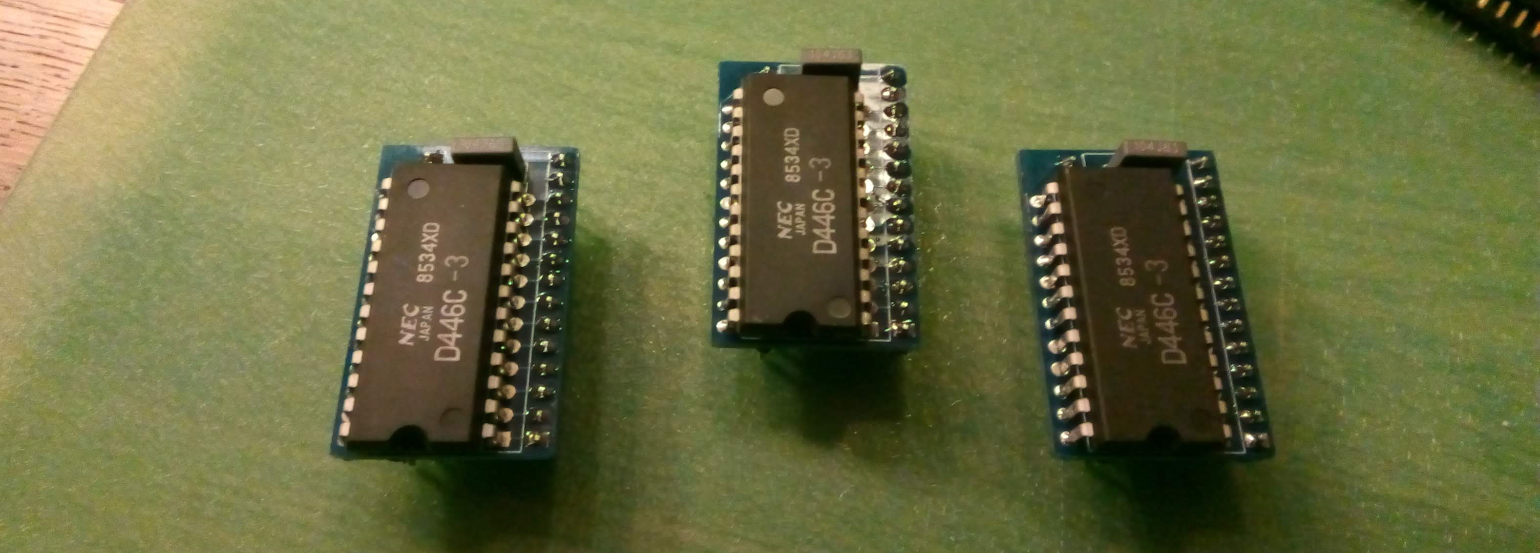
Th RAM adapter PCBs have arrived, and assembling was easy. So it's time for the next step. After inserting them, I switched on the power, and got this on my screen:
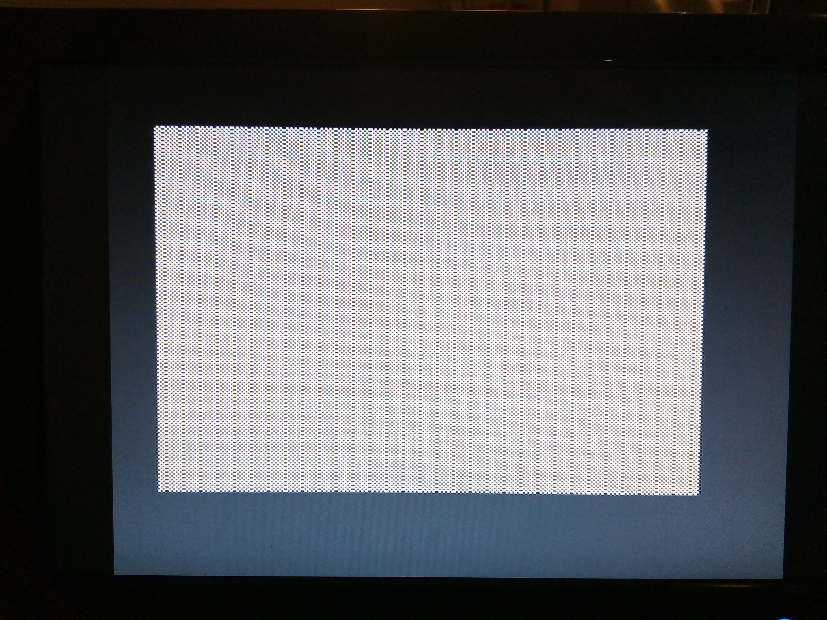
Looks like the video circuit is working, but the content seems incorrect. Turns out the that Z80 does not get a clock, so the processor is not running at all. Which means that the video circuit on its own is capable of generating this pattern, which I did not expect.
But why is there no clock? Tracing the signal from the oscillator, it seems to stop at the base of the transistor that should buffer the signal :
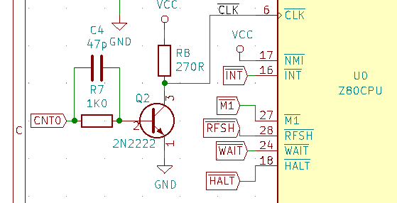
I can see the signal on the base, but there is nothing on the collector. How can ? This is the most basic transistor circuit possible, it should work ! Turns out it doesn't, because I underestimated the frequency involved. 3.5 MHz does not sound like a a high frequency these days, but it is way beyond the capacity of a 2N2222. When used as a switching transistor, the switching times go up to 250nS, which is just too slow. That's why the original Jupiter uses a 2N2369 which has switching times of 12 nS. I did not have that available, so I decide to use a BS170, a N-Channel mosfet which should be capable of switching up to 200 MHz. And that works great. Now the clock on the Z80 is square and clean.
After switching it on again it looks like something happens. The screen is now filled with a different pattern and there are some unrecognisable blobs at the bottom row. But typing on the keyboard does change the content of the bottom row, and when pressing enter I can see the screen scroll, although the general pattern changes. The fact that it responds to the keyboard, and that this changes the screen tells me that the processor is working (after all, it is scanning the keyboard). So the problem must be in the video circuit itself, or the connections to the video RAM chips. After meticulously checking all connections from ant to the RAM, and comparing them (again) with the original schematics I found no mistakes or missing connections. Probing around with the scope however shows a lot of noise an glitches, especially around the 74HC166 shift register. Extra decoupling does not change anything, so I was thinking adding some kind of filtering to the data lines.
Then I realised that I used all 74HC series logic on my board, while every schematic (including mine) has the 74LS series. From my past experiences I do know that the HC and LS series are definitely different. The logic (obviously) is the same, but since the HC series are all CMOS, and the LS uses low power schottky their electronic behaviour may be different. It could well be that using the 1K series resistors in the data lines may not be a good idea for HC variants.
So I could try to solve that, or simply order a full set of 74LS chips so I can simply exchange and compare. After all, these chips are very cheap (between 0.25 and 1 Euro a piece). It only means I have to wait another week before the next test run.
Meanwhile, while going through the Jupiter ACE section on the K? Forum I also noticed that someone else had problems with the video, which were solved after removing C8. This capacitor is there to extend, or clean up , the 'WAIT' signal. Apparently a wrong WAIT signal can delay the Z80 too long so the timing for writing to the video memory is wrong, which could cause a screen similar to what I got. Maybe worth trying, if swapping the chips does not work.
Discussions
Become a Hackaday.io Member
Create an account to leave a comment. Already have an account? Log In.