 ben01110000
The flex cube contains 4 layers; 3 layers containing 9 LEDs each and 1 containing power and control.
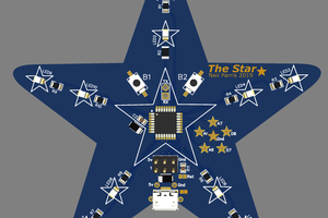
A big part of any LED cube is... the LEDs! I chose the APA102-2020 as they are tiny and serial-addressable. Getting 9 on each layer wasn't too much hassle, however when routing was nearly complete I realised that the centre LED on each layer was almost completely obscured and so added four cut-outs to the top two layers. I'm sure this won't make much difference but worth a try. I've scattered decoupling caps throughout the layers, however they tend to clash with components on other layers when it get folded.
The control is provided by a SAMD21, which is overkill to just drive some LEDs but it's what i'm familiar with so that's why it's on the PCB (It could have been far simpler to go with a 5V micro for both power supply and level-shift reasons but oh-well).
Power is provided over USB with the 3.3v supply for the SAMD provided by a simple linear reg. I've seen the APA102s sink the best part of 100mA at fully brightness & displaying white, so 27 of them might be a little outside what a standard USB power supply can provide, but i'm sure it'll be fine.
I've used the MMA8451 as the accelerometer. This was a last minute decision, and it probably shows in how it's been squeezed into place.(I'll try and add some more detailed images of the control layer). But if it works i think that it'll be worthwhile in adding some user interaction.
I used Altium for the schematic capture and layout. This worked really well as Altium has inbuilt flex PCB support, enabling you to define bend lines, flexible/rigid regions, and to see how the the PCB looks as it is folded, which is really useful for checking part-to-part clearances as well as any unintended clearances.
I tried to stick with flex-PCB best practice where possible, but 2 square inches isn't much room and I decided that more space on the PCB would be better than completely following the best practice on minimum bend radii as long as I only bend them once (maybe). I tried to alleviate this by adding hatched fills to the bend areas, and only routing on one side of the PCB. I'll let you know how robust this seems to be if i get my hands on any...
As i couldn't find room to add mounting holes for standoffs there's no real way to make the PCB self-supporting as-is. This is definitely a project that might benefit from stiffeners or from a rigid-flex layer stack, but also those both sound like a lot more effort. To support it in its current form I'd like to try a resin pour, maybe with a clear 3D printed frame to hold it in place. Both of those are a little outside of my current knowledge, if you've got any thoughts then hit me up!
next steps:
If this turns out alright, i'd consider making a slightly larger version. Probably still 3x3x3 but trying to get a better "aspect ratio" and maybe adding in room for standoffs, battery and more sensors, any maybe add some strain relief to the bending sections.

 Neil Parris
 fl@C@
fl@C@
 M Leone
 Brian Lough
Have you actually made it? Can you see the LEDs through the substrate?