 Bud Bennett
I had not used a SPI interface with the Raspberry Pi before starting on this circuit. The documentation for the Python implementation is sparse compared to what's available for C. It required a day of tinkering to obtain the first valid data from the ADC. I had to get my Rigol oscilloscope involved. After that things progressed quickly.
At first, the only data returned from the ADC was 0xFF. I found two things that needed understanding before the data would come. The Raspberry Pi has a wicked fast SPI interface. It was cruising along at more than 100MHz, but the poor ADC couldn't go faster than 5MHz, according to the spec. I had to slow it down with the following line of code, which sets the SCLK frequency at 1MHz.
spi.max_speed_hz=(1000000)
Now I could see square waves pinging between VDD and GND.
Next I determined that the SPI had to keep clocking data into the ADC after it was given a command byte in order to clock data out of the ADC and into the Raspberry Pi. There isn't a built-in read or write command for the SPI protocol -- it's doing both at the same time. So if you need to just write a single-byte command to start an ADC conversion it is pretty simple:
spi.xfer([Convert2p5])
If you need to read or write data from/to a register then the SPI must send a command byte followed by the required bytes for the read/write:
r = spi.xfer2([regDATA, 0, 0, 0]) # for a read
spi.xfer2([regSOC, 0x1f, 0xCA, 0x02]) # for a write
And the last thing to understand is that the data comes little-endian. For the read statement above, r is a list of 4 bytes, for example:
r = [0xff, 0x0f, 0x12, 0xD1]
r[0] can be tossed, r[1] is the MSB and r[3] is the LSB.
Here's the code that I cobbled together to get an understanding of the ADC:
#!/usr/bin/env python
#
# Bitbang'd SPI interface with an MCP3008 ADC device
# MCP3008 is 8-channel 10-bit analog to digital converter
#  Connections are:
#     CLK => SCLK
#     DOUT =>  MISO
#     DIN => MOSI
#     CS => CE0

import time
import sys
import spidev
import math

SelfCalibration = 0x90
SystemOffsetCal = 0xA0
SystemGainCal = 0xB0
Convert2p5 = 0x81
regSTAT = 0xC0
regCTRL1 = 0xC2
regCTRL2 = 0xC4
regCTRL3 = 0xC6
regDATA = 0xC9
regSOC = 0xCA
regSGC = 0xCC


spi = spidev.SpiDev()
spi.open(0,0)
spi.max_speed_hz=(1000000)
#spi.mode = 0b11

def buildReadCommand(channel):
    startBit = 0x01
    singleEnded = 0x08

    return [startBit, singleEnded|(channel<<4), 0]

def processAdcValue(result):
    '''Take in result as array of three bytes.
       Return the two lowest bits of the 2nd byte and
       all of the third byte'''
    byte2 = (result[1] & 0x03)
    return (byte2 << 8) | result[2]

def command(register):
    spi.xfer(register)
    return

def writeReg(register, dataList):
    registerData = [register]
    for data in dataList:
        registerData.append(data)
    spi.xfer2(registerData)

def readReg(register, dataList):
    registerData = [register+1]
    for data in dataList:
        registerData.append(data)
    r = spi.xfer2(registerData)
    return r

def readAdc():
    r = spi.xfer2([regDATA,0,0,0])
    result = r[1]*256*256 + r[2]*256 + r[3]
    if result > (2**23)-1:
        result = (result - 2**24)
    return result

def convert2volts(data):
    v = data/(2**23-1) * 3.6
    return v

def meanstdv(x):
    """
    Calculate mean and standard deviation of data x[]:
    mean = {\sum_i x_i \over n}
    std = math.sqrt(\sum_i (x_i - mean)^2 \over n-1)
    """
    n, mean, std = len(x), 0, 0
    for a in x:
        mean = mean + a
    mean = mean / float(n)
    for a in x:
        std = std + (a - mean)**2
    if(n > 1):
        std = math.sqrt(std / float(n-1))
    else:
        std = 0.0
    return mean, std


if __name__ == '__main__':
    writeReg(regSOC,[0,0,0])
    time.sleep(0.1)
    CTRL1 = readReg(regCTRL1, [0])
    print("CTRL1 = {}".format(hex(CTRL1[1])))
    CTRL3 = readReg(regCTRL3, [0])
    print("CTRL3 = {}".format(hex(CTRL3[1])))
    time.sleep(1)
    print("Enable Self Calibration")
    writeReg(regCTRL3,[0x18])
    time.sleep(1)
    CTRL3 = readReg(regCTRL3,[0])
    print("CTRL3 = {}".format(hex(CTRL3[1])))
    writeReg(regCTRL1,[0x02])
    time.sleep(1)
    CTRL1 = readReg(regCTRL1, [0])
    print("CTRL1 = {}".format(hex(CTRL1[1])))
    SOC = readReg(regSOC,[0,0,0])
    print("System Offset = {0}".format(SOC))
    SGC = readReg(regSGC,[0,0,0])
    print("System Gain = {0}".format(SGC))
    print("Performing System Self Calibration...")
    command([SelfCalibration])
    time.sleep(1)
    SOC = readReg(regSOC,[0,0,0])
    print("System Offset = {0}".format(SOC))
    #print("Writing 0x0f to SOC register")
    #writeReg(regSOC,[0,0x0C,0x0F])
    time.sleep(0.1)
    SOC = readReg(regSOC,[0,0,0])
    print("System Offset = {0}".format(SOC))
    SGC = readReg(regSGC,[0xff,0xff,0xff])
    print("System Gain = {0}".format(SGC))

    result_array = []
    oldSTAT = 0x00
    n = 0
    sd_avg2 = float(0)
    try:
        while True:
            STAT = readReg(regSTAT,[0])
            if (STAT != oldSTAT):
                print("STAT = {}".format(hex(STAT[1])))
                oldSTAT = STAT
            val = readAdc()
            print ("ADC Result: {0:.7f}".format(convert2volts(val)))
            result_array.append(convert2volts(val))
            if (len(result_array) == 20):
                n += 1
                mean,sd = meanstdv(result_array)
                result_array = []
                print("\n\tVoltage mean: {0:.7f} V".format(mean))
                print("\tVoltage std dev: {0:.2f} uV".format(1000000*sd))
                dnr = 20 * math.log(1.6 * 3.6/sd,10)
                nfbits = math.log(1.6 * 3.6/(6 * sd),2)
                print("\tDynamic Range = {0:.1f}db, ({1:.2f} bits)".format(dnr, nfbits))
                sd_avg2 += sd**2
                sd_avg = math.sqrt(sd_avg2/n)
                print("\tAvg Std Dev = {0:.2f} uV".format(1000000*sd_avg))
                avg_dnr = 20*math.log(1.6*3.6/sd_avg,10)
                avg_nfbits = math.log(1.6 * 3.6/(6 * sd_avg),2)
                print("\tAvg Dynamic Range = {0:.1f}db, ({1:.2f} bits)\n".format(avg_dnr, avg_nfbits))

            command([Convert2p5])
            time.sleep(.5)
    except KeyboardInterrupt:
        spi.close()
        sys.exit(0)
I will clean it up later and convert it to a Class module.
I started out perfoming a conversion every 5 seconds, but found that it took too long to accumulate the data for the standard deviation and mean -- the part was drifting over the long acquisition time. It was better to collect about 20 samples in 10 seconds. I then added a scheme to average the standard deviation values across all of the collected sample groups. This approach acts like a high pass filter for very low frequencies and therefore eliminates the drift terms.
This is the output near the end of a half-hour run time:
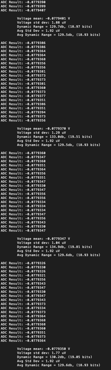
Right away you notice that the circuit is not producing 22-bits of NFDNR. I have a couple of explanations for that.
- The circuit was built with components that were not optimized for noise.
- The GS8591 has 33nV/√Hz noise density instead of the 13nV/√Hz of the MCP6V81.
- The 1/f noise component of the OPA376 opamp used in the input integrator wipes out everything else.
The input integrator needs to be a zero-drift chopper opamp with no 1/f component at DC. Here's the difference between the OPA376 and the MCP6V81:
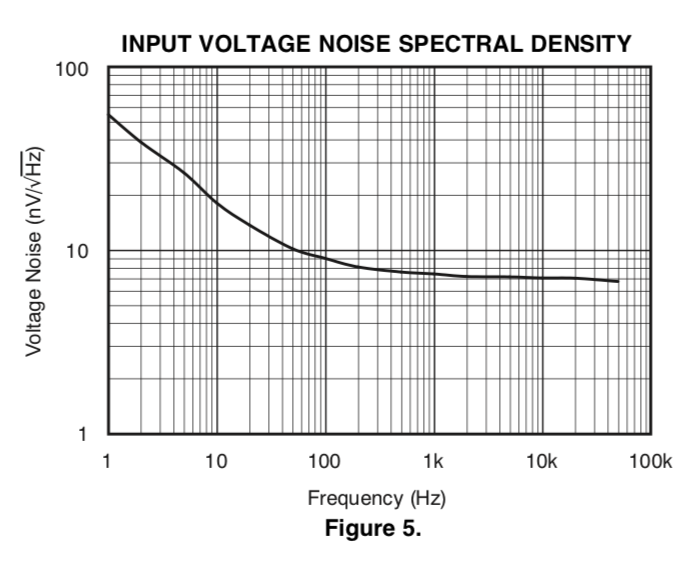
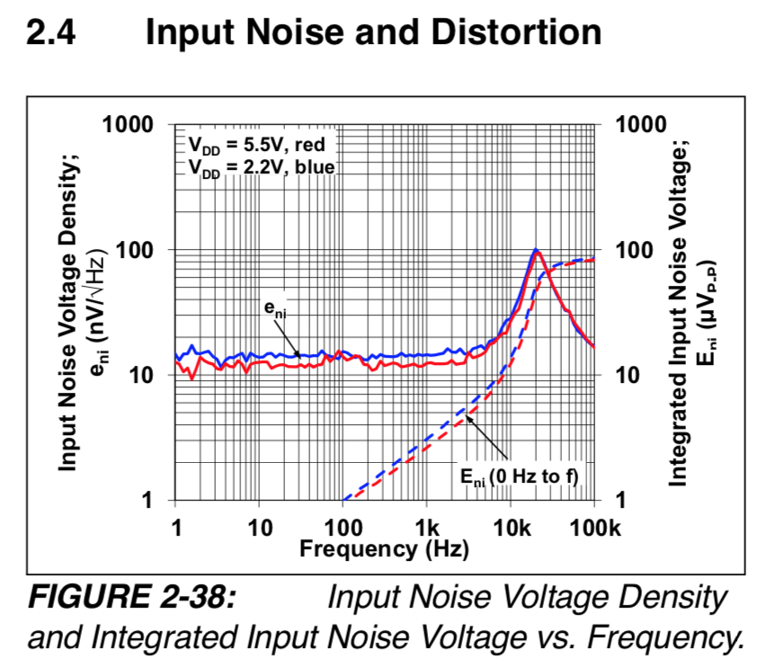
The OPA376 1/f noise density is nearly 550nV/√Hz at 0.1Hz, if you just continue the trend below 1Hz. This noise gets multiplied by nearly 4x when referred to the input of the ADC. The MCP6V81 noise density is only 13nV/√Hz to DC. It has a spike between 3kHz and 100kHz, but this should get taken out by the demodulator. I expect this to make a huge difference in the noise performance of the next board.
By accounting for the component values used in this circuit, following the guidelines of my log about noise analysis, I calculated the total noise of this circuit, with no capacitors connected to the inputs, to be about 2µVrms (18.6 bits NFDNR). That's pretty close to what the ADC is reporting. The next board will have optimized components and should perform closer to expected design targets. I must now order some more parts from Digikey...
Discussions
Become a Hackaday.io Member
Create an account to leave a comment. Already have an account? Log In.