 Lloyd Konneker
The project is a tiny, solar powered, motorized spinner, fabricated from a single, flexible PCB by folding into a rounded cube. An electronic wearable, an earring.
Status: I have tested the electronic design using rigid PCB but that requires hand building and soldering of the solar cells. This design is simpler to fabricate. I have not tuned the circuit parameters to final, optimal values.
History: the design derives from very common “solar bugs” using pager vibrators. It uses the common, simple, “solar miller” circuit design that pulses power to a motor whenever it can. Here, the motor has no off-center weight, and the unit is suspended by a thread to the shaft of the motor.
Performance: the solar cells are very small, not efficient, and don’t all face the light. The unit turns occasionally in outdoor, bright sky, shade (about 10k lux) and turns more often in direct sun (100k lux.) It doesn’t turn even in very bright indoor light, such as office light (1k lux.)
Alternatives: The design might perform better if I could find better solar cells than this design’s commonly available photodiodes pressed into service as solar cells. The design might instead use flexible film solar cells, cut into a ring.
Fabrication: The design uses surface mount (SMD) parts (except for the motor leads.) But it can also be hand soldered. The parts are all available from DigiKey, except for the motor, which usually is available from many vendors, like Jameco or Goldmine. The bill of materials is in an html file. The smallest parts are 602 size, which are not too hard to handle.
In blogs I discuss design issues with flexible PCB, how the circuit works, and how to tune the design.
The bill of materials BOM is in an html file in the github repository.


 Simon Merrett
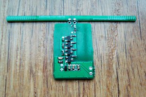
 Jurist
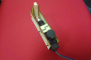
 adria.junyent-ferre
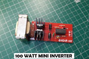
 Sagar 001
:)